Performance-Based EMC Design of Electronic Systems
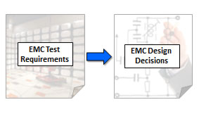
When you're designing an electronic system, how do you know that your design will meet all of its EMC requirements? Is that filter on your interface connector really necessary? Is it sufficient? Do you need to shield the enclosure? Clearly, the answer to these questions must depend on the EMC design requirements. Will the product have to meet FCC requirements or military requirements? Will it have to operate in a 10 V/m field or a 100 V/m field?
For the most part, current EMC design practices are not explicitly tied to design requirements. Design guidelines play a big role in the EMC design process, but these guidelines are rarely tied to specific EMC performance requirements. The goal of this project is to develop basic models and design procedures that will allow engineers to make good board-level and system-level design decisions based on the product's EMC requirements. This effort started 18 years ago with the EMC Expert System project, which developed algorithms to help computers find EMC problems in much the same way that EMC experts find problems when reviewing a board layout. Eventually, it became evident that human experts relied heavily on "rules-of-thumb" based on their experience with previous designs. It was neither effective nor practical to teach computers these rules-of-thumb, because the blind application of these rules often led to poor designs. On the other hand, computers don't need to rely on rules like this, because they are capable of performing rather complex calculations on the fly. For example, a human expert might use a rule that says, "there should be at least 5 mm of spacing between a clock trace and an I/O trace." A computer with access to all the parameters of interest can calculate exactly how much crosstalk can occur for a particular geometry, and then determine the worst case outcome of that coupling.
Eventually, the EMC Expert System Project resulted in the development of algorithms for a Maximum Radiated EMissions Calculator (MREMC). This calculator determines the maximum possible radiated emissions that a particular source/coupling-path/antenna combination on a printed circuit board is capable of producing. For all unknown quantities, the worst-case is assumed. For example, if there are attached cables or metallic enclosures with unknown geometries, the calculations are done as though these structures were optimally configured to maximize the radiated emissions. If digital signal rise-times are uncontrolled or otherwise unknown, the shortest possible rise-time is used for the calculations. Even with these worst-case assumptions, very few of the potential source/coupling-path/antenna combinations on a well-designed board will actually be capable of causing a radiated emissions problem. The MREMC algorithms are capable of evaluating thousands of combinations to quickly identify which components and structures on a board are potentially a problem.
A unique feature of the MREMC algorithms is that they tie design parameters directly to the radiated emissions requirements for the product. Therefore, the design recommendations derived from applying these algorithms may be different depending on which emission requirements must be met. The current project extends this idea to other EMC requirements including RF susceptibility, transient susceptibility and conducted emissions requirements. For example, a 100-MHz, 10-V/m field incident on a product with attached cables in a typical EMC test configuration can capture (at most) 6 watts of power. Depending on the system and board geometries, this power can be translated to maximum voltages and currents on virtually any circuit in the system. This information can then be compared to the known immunity levels of each component and circuit to determine if anything might be vulnerable to this field. Any vulnerabilities that are found can be corrected by making design changes or examined more closely to determine whether the actual coupling is likely to be much less than the maximum possible coupling.
The algorithms are all closed-form calculations, so tens of thousands of possible interactions can be evaluated in a short time. Potential
EMC
problems can be quickly identified and flagged. The process should ensure that cost and effort isn't invested in shields, filters and other EMC precautions that aren't really needed to meet the product's requirements. Ultimately, a design that passes all of the criteria according to the algorithms, should meet all of its EMC requirements the first time it is tested.
Publications
- T. Hubing, “Performance-based EMC Design using a Maximum Radiated Emissions Calculator,” Journal of Electromagnetic Engineering and Science, vol. 13, no. 4, Dec. 2013, pp. 199-207.
- C. Zhu and T. Hubing, “Maximum Radiated Emission Calculator: Common-Mode EMI Algorithm,” Clemson Vehicular Electronics Laboratory Technical Report, CVEL-13-051, Dec. 23, 2013.
- C. Zhu and T. Hubing, “Maximum Radiated Emission Calculator: Power Bus Algorithm,” Clemson Vehicular Electronics Laboratory Technical Report, CVEL-13-053, Oct. 12, 2013.
- C. Zhu and T. Hubing, “Maximum Radiated Emission Calculator: Differential-Mode EMI Algorithm,” Clemson Vehicular Electronics Laboratory Technical Report, CVEL-13-052, Oct. 12, 2013.
- T. Hubing, "Designing Automotive Components for Guaranteed Compliance with Electromagnetic Compatibility Requirements," In Compliance Magazine, May 2013.
- X. He and T. Hubing, “A Closed-Form Expression for Estimating the Maximum Radiated Emissions from a Heatsink on a Printed Circuit Board,” IEEE Trans. on Electromagnetic Compatibility, vol. 54, no. 1, Feb. 2012, pp. 205-211.
- C. Su and T. Hubing, “Calculating Radiated Emissions due to I/O Line Coupling on Printed Circuit Boards using the Imbalance Difference Method,” IEEE Trans. on Electromagnetic Compatibility, vol. 54, no. 1, Feb. 2012, pp. 212-217.
- C. Su and T. Hubing, “Improvements to a Method for Estimating the Maximum Radiated Emissions from PCBs with Cables,” IEEE Trans. on Electromagnetic Compatibility, vol. 53, no. 4, Nov. 2011, pp. 1087-1091.
- X. He, T. Hubing, H. Ke, N. Kobayashi, K. Morishita and T. Harada, “Calculation of Optimal Ground Post Resistance for Reducing Emissions from Chassis-Mounted Printed Circuit Boards,” IEEE Trans. on Electromagnetic Compatibility, vol. 53, no. 2, May 2011, pp. 475-481.
- C. Su and T. Hubing, “Imbalance Difference Model for Common-Mode Radiation from Printed Circuit Boards,” IEEE Trans. on Electromagnetic Compatibility, vol. 53, no. 1, Feb. 2011, pp. 150-156.
- X. Dong, H. Weng, D. G. Beetner, T. Hubing, “Approximation of Worst-Case Crosstalk at High Frequencies,” IEEE Trans. on Electromagnetic Compatibility, vol. 53, no. 1, Feb. 2011, pp. 202-208.
- H. Zeng, H. Ke, G. Burbui and T. Hubing, “Determining the Maximum Allowable Power Bus Voltage to Ensure Compliance with a Given Radiated Emissions Specification,” IEEE Trans. on Electromagnetic Compatibility, vol. 51, no. 3, Aug. 2009, pp. 868-872.
- S. Deng, T. Hubing and D. Beetner, “Estimating Maximum Radiated Emissions from Printed Circuit Boards with an Attached Cable,” IEEE Trans. on Electromagnetic Compatibility, vol. 50, no. 1, Feb. 2008, pp. 215-218.
- Y. Fu and T. Hubing, “Analysis of Radiated Emissions from a Printed Circuit Board using Expert System Algorithms,” IEEE Trans. on Electromagnetic Compatibility, vol. 49, no. 1, Feb. 2007, pp. 68-75.
- H. Shim and T. Hubing, “A Closed-Form Expression for Estimating Radiated Emissions from the Power Planes in a Populated Printed Circuit Board,”IEEE Trans. on Electromagnetic Compatibility, vol. 48, no. 1, Feb. 2006, pp. 74-81.
- H. Shim and T. Hubing, “Model for Estimating Radiated Emissions from a Printed Circuit Board with Attached Cables Due to Voltage-Driven Sources,” IEEE Trans. on Electromagnetic Compatibility, vol. 47, no. 4, Nov. 2005, pp. 899-907.
- H. Shim and T. Hubing, “Derivation of a Closed-Form Approximate Expression for the Self-Capacitance of a Printed Circuit Board Trace,” IEEE Trans. on Electromagnetic Compatibility, vol. 47, no. 4, Nov. 2005, pp. 1004-1008.
- H. Shim, T. Hubing, T. Van Doren, R. DuBroff, J. Drewniak, D. Pommerenke and R. Kaires, “Expert System Algorithms for Identifying Radiated Emission Problems in Printed Circuit Boards,” Proc. of the 2004 IEEE International Symp. on Electromagnetic Compatibility, Santa Clara, CA, USA, Aug. 2004, pp. 57-62.
- M. Xu and T. Hubing, “The Development of a Closed-Form Expression for the Input Impedance of Power-Return Plane Structures,”IEEE Trans. on Electromagnetic Compatibility, vol. 45, no. 3, Aug. 2003, pp. 478-485.
- M. Xu and T. Hubing, “Estimating the Power Bus Impedance of Printed Circuit Boards with Embedded Capacitance,” IEEE Transactions on Advanced Packaging, vol. 25, no. 3, Aug. 2002, pp. 424-432.
- M. Li, J. Drewniak, S. Radu, J. Nuebel, T. Hubing, R. DuBroff and T. Van Doren, “An EMI Estimate for Shielding-Enclosure Evaluation,” IEEE Trans. on Electromagnetic Compatibility, vol. 43, no. 3, Aug. 2001, pp. 295-304.
- D. M. Hockanson, J. L. Drewniak, T. H. Hubing, T. P. Van Doren, F. Sha, C. W. Lam, and L. Rubin, "Quantifying EMI resulting from finite-impedance reference planes,"IEEE Trans. on Electromagnetic Compatibility, vol. 39, no. 4, Nov. 1997, pp. 286-297.
- N. Kashyap, T. Hubing, J. Drewniak, and T. Van Doren, "An expert system for predicting radiated EMI from PCBs," Proc. of the 1997 IEEE International Symposium on Electromagnetic Compatibility, Austin, TX, Aug. 1997, pp. 444-449.
- D. M. Hockanson, J. L. Drewniak, T. H. Hubing, T. P. Van Doren, F. Sha, and M. Wilhelm, "Investigation of Fundamental EMI Source Mechanisms Driving Common‑Mode Radiation from Printed Circuit Boards with Attached Cables," IEEE Trans. on Electromagnetic Compatibility, vol. 38, no. 4, Nov. 1996, pp. 557-566.
- T. Hubing, J. Drewniak, T. Van Doren, and N. Kashyap, "An Expert System Approach to EMC Modeling," Proc. of the 1996 IEEE International Symposium on Electromagnetic Compatibility, Santa Clara, CA, Aug. 1996, pp. 200‑203.
|


