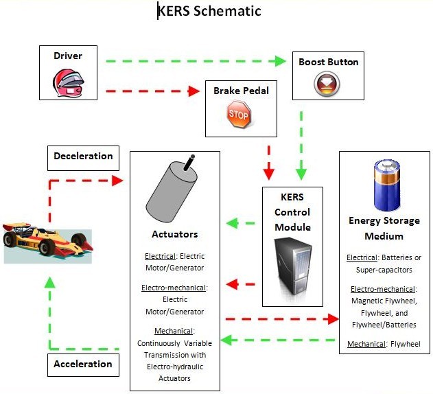
Kinetic energy recovery systems (KERS) store energy only when the vehicle is braking and return it when accelerating. During braking, energy is wasted because kinetic energy is mostly converted into heat energy that is dissipated into the environment. Vehicles with KERS are able to harness some of this kinetic energy and in doing so will assist in braking. KERS vehicles still dissipate heat energy when braking but less is wasted since some energy is stored in the vehicle. By a touch of a button, this stored energy is converted back into kinetic energy giving the vehicle extra boosts of power.
KERS requires two basic elements. First, a way to store and then return energy to the powertrain and second, a place to store this energy. There are three basic types of KERS systems: electronic, electro-mechanical and mechanical. The main difference between them is in the way they convert the energy and how it is stored within the vehicle.
Electronic KERS
In electronic KERS, braking rotational force is captured by an electric motor / generator unit (MGU) mounted to the engines crankshaft. This MGU takes the electrical energy that it converts from kinetic energy and stores it in batteries. The boost button then summons the electrical energy in the batteries to power the MGU. The most difficult part in designing electronic KERS is how to store the electrical energy. Most racing systems use a lithium battery, which is essentially a large mobile phone battery. Batteries become hot when charging them so many of the KERS cars have more cooling ducts since charging will occur multiple times throughout a race. Super-capacitors can also be used to store electrical energy instead of batteries, they run cooler and are debatably more efficient.
Electro-mechanical KERS
In electro-mechanical KERS energy is not stored in batteries or super-capacitors, instead it spins a flywheel to store the energy kinetically. This system is effectively an electro-mechanical battery.
There is limited space in a racecar so the unit is small and light. Therefore, the flywheel spins very fast to speeds of 50,000 - 160,000 rpm to achieve sufficient energy density. Aerodynamic losses and heat buildup are minimized by containing the spinning flywheel in a vacuum environment. The flywheel in this system is a magnetically loaded composite (MLC). The flywheel remains one piece at these high speeds because it is wound with high strength fibers. The fibers have metal particles embedded in them that allows the flywheel to be magnetized as a permanent magnet.
The flywheel will perform similarly to an MGU. As the flywheel spins, it can induce a current in the stator releasing electricity or it can spin like a motor when current flows from the stator. This flywheel is used in conjunction with an MGU attached to the gearbox which supplies electrical energy to the flywheel from the road and returns it to the gearbox for acceleration at the touch of a button. Not all flywheels used in the electro-mechanical KERS are permanent magnets. Instead, these systems use two MGUs, one near the flywheel and another at the gearbox. Some systems use flywheels and batteries together to store energy.
Mechanical KERS
The mechanical KERS system has a flywheel as the energy storage device but it does away with MGUs by replacing them with a transmission to control and transfer the energy to and from the driveline. The kinetic energy of the vehicle end up as kinetic energy of a rotating flywheel through the use of shafts and gears. Unlike electronic KERS, this method of storage prevents the need to transform energy from one type to another. Each energy conversion in electronic KERS brings its own losses and the overall efficiency is poor compared to mechanical storage. To cope with the continuous change in speed ratio between the flywheel and road-wheels, a continuously variable transmission (CVT) is used, which is managed by an electro-hydraulic control system. A clutch allows disengagement of the device when not in use.
KERS in Formula 1
The FIA (Federation Internationale L"Automobile) have authorized hybrid drivetrains in Formula 1 racing for the 2009 racing season. The intent is to use the engineering resources of the Formula 1 community to develop hybrid technology for use not only in motorsport but also eventually in road vehicles. The hybrid systems specifications have been kept to a minimum, especially the type of hybrid system. This was done purposely to lead to the study and development of various alternatives for electrical hybrids which has been met with success.
With a focus on safety, the FIA have specified a limit on both the power rating of the hybrid system at 60kW and the quantity of energy transfer per lap at 400kJ. This translates into an extra 85bhp for just under seven seconds, which makes overtaking another vehicle on the track easier and the race much more interesting. The 60kW/400kJ limits in Formula 1 will not apply to road cars. Road cars will safely have more power and energy transfer due to their larger weight when compared with racecars, which will provide them with significant benefits.
There is more than one type of KERS used in motorsports. The most common is the electronic system built by the Italian company Magneti Marelli, which is used by Red Bull, Toro Rosso, Ferrari, Renault and Toyota. Although races have been won with this technology, KERS will be removed from the 2010 Formula 1 season due to its high cost.
Dissimilar to Regenerative Braking
Traditional hybrids acquire electrical energy from braking in a similar way that electrical KERS equipped vehicles do but the difference lies in how the energy is reused. While KERS quickly re-injects the energy back into the powertrain to provide additional power boost in conjunction with the engine, the traditional hybrid saves the energy to power the electric powertrain. KERS is different from traditional hybrids in that the stop start functionality is not a prime goal of the system. KERS work very well in conjunction with engine mounted Stop/Start systems, or it can be engine mounted and used for stop start functionality. The KERS hybrid system cannot be "charged" by the engine directly, which is the requirement that has lead to its name, "KERS".