Fuel injection is a method of introducing fuel into an internal combustion engine. In North America, fuel injection methods have replaced carburetors, with the Subaru Justy being the last car to be sold with carburetors in 1990. Fuel injectors deliver fuel more precisely than carburetors. They are electromechanical actuators with a small nozzle that supplies high pressure fuel to the engine. They are powered by a 12 V supply either from the fuel injection relay or the ECM. In short, injectors are solenoid operated valves that use Pulse Width Modulated (PWM) signals from the Engine Control Unit to open or close a valve that permits or blocks fuel flow to the engine. A well designed fuel injector ensures quick and complete combustion of fuel. The injector atomizes fuel into very fine droplets and hence increases the surface area. This results in better mixing and subsequent combustion, which leads to better fuel economy and power. The operation and control of fuel injectors have a profound impact on their durability and long term performance.
Operation
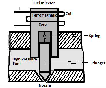
A basic diagram of an injector is shown above. It consists of a ferromagnetic core that is surrounded by a coil. A magnetic plunger is attached to the core with help of a helical spring. The plunger moves up and down to allow and block the flow of pressurized fuel. Fuel is stored in a pressurized fuel chamber and flows to the cylinder through a nozzle. The nozzle is designed to atomize the fuel.
The major components of an injector are the valve housing, injector spindle, magnetic plunger to which spindle is connected, helical spring and the solenoid coil. With no current flow, the solenoid is not excited and the plunger is forced down against the nozzle by the spring. Hence fuel stored in the pressurized fuel chamber is blocked from flowing to the cylinder. On receiving current pulses from the ECU, the solenoid coil is excited and the plunger moves up, lifting the spindle by 0.15mm, allowing fuel flow through the nozzle. Typical injection times range from about 1.5 to 10 ms.
Fuel injector signal
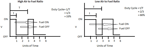
The mass of fuel injected per cycle is controlled by varying the duration of the current pulse that excites the solenoid coils. The ECM sets the excitation pulse duration. Consider an idealized fuel injector excitation waveform as shown above, the injector is open when the applied voltage is ON and closes when the voltage is OFF. The control voltage that operates the injector is a binary pulse train. The ratio of on time t to the total period of pulse train T is called the duty cycle. The injector is energized for time t to allow fuel flow through nozzle. The injector is deenergized for the remaining period. A low duty cycle is used for a high air/fuel ratio (lean mixture) and a high duty cycle is used for a low air/fuel ratio (rich mixture).
Advancements
Some newer fuel injectors emply a piezo-actuator instead of a solenoid valve. This requires some modifications in design in order to maximize the advantages of the piezo feature. The nozzle needle is controlled hydraulically by the actuator and there is no mechanical connection between actuator and nozzle needle. This approach eliminates any sort of friction and any elastic deformation of the connection elements. Piezo actuators are faster than solenoid valves and require less structural space. The weight is reduced by approximately 50 percent and the intervals between injections can be reduced. The use of piezo-actuators can potentially reduce fuel consumption by up to 15 percent