Camless Engines
by Nitant Shroff, Clemson Automotive Engineering Graduate Student
- Basic Description
-
Since the invention of internal combustion engines, camshafts have been used to operate the valves on the cylinder head to bring in air and fuel and expel exhaust gases. The conventional valve train has its limitations: the single lobed cam is designed to operate the valves at only specific periods of the Otto cycle, thus preventing the engine from achieving maximum torque at higher rpms. The opening and closing of the valves is constrained by the geometry of the cam profile. The concept of camless engines allows for greater optimization of overall engine performance during different phases of running.
- Working
-
Camless engines generally employ one of two types of camless actuators: electro-hydraulic or electro-mechanical valve actuators. The actuators receive input from the ECU via a dedicated CAN bus to open and close the poppet valves at a prescribed crankshaft angle timing, transition time and lift, matching the valve timing request sent by the ECU. Feedback is then sent by the actuators through the CAN bus to verify the actual occurrence of the operation.
Electromechanical Actuators:
Electromechanical actuators are generally made with two solenoids and two springs. As can be seen in Figure 1 the ECM receives input from the crankshaft position sensor to close the valve, which activates Solenoid 1 by taking current from the battery. The current is passed through a pulse width modulator which tunes the amplitude of the current to control the speed of valve seating. The magnetic field created by Solenoid 1 attracts the armature in the upper position. Spring 1 is compressed and thus closes the valve. Solenoid 2 pulls the armature down to open the valve as shown in Figure 2.
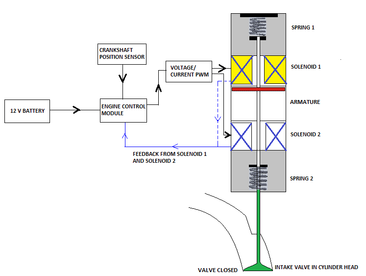
Figure 1: Valve Closed
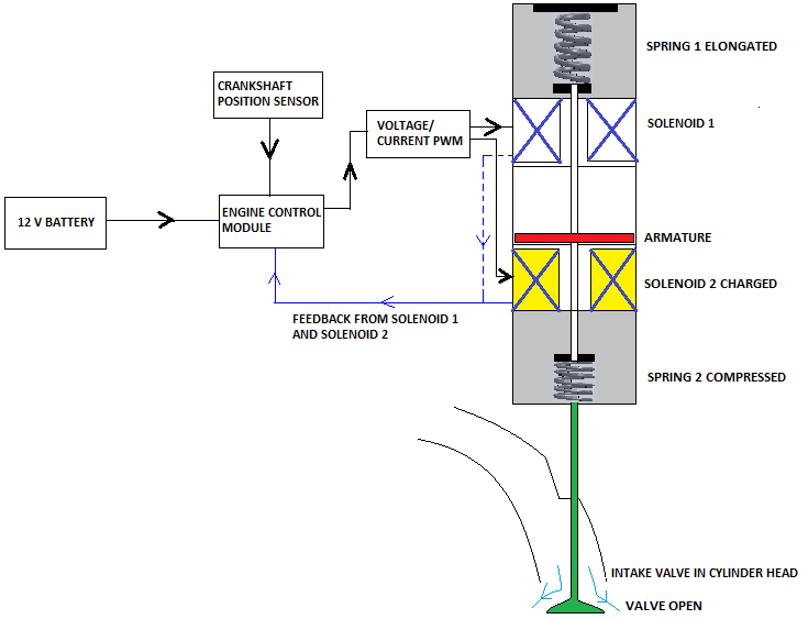
Figure 2: Valve Open
- Advantages:
-
- Enables the development of higher torque throughout the entire rev range which in turn improves fuel economy
-
- Cylinder Deactivation can be achieved during the idling phase
-
- Exhaust gas recirculation is improved
-
- Reduces friction losses
-
- Reduces the inertia of moving parts
- Disadvantages:
-
- High Cost
-
- Increased power consumption
-
- Air gap between the solenoids may demand a higher magnitude of current during certain periods
-
- The control strategy for valve seating velocity needs to be modified
- Alternative designs:
-
- The armature can be eliminated and the two solenoids in the above design can be replaced with two armatures each having a current carrying coil. The remaining circuitry remains the same. The magnetic field generated in one armature is opposes the other thus retracting or elongating the spring as per the request of the ECM
- To eliminate the camshaft, poppet valves can be replaced by electromechanical ball valves [1]
- Electrohydraulic valve train can also be employed to eliminate the camshaft [1]
- Sensors
- Crankshaft Position Sensor, Throttle Position Sensor
- Actuators
- Solenoids
- Manufacturers
- Sturman Industries
- For More Information
- [1] Camless Engines, Autospeed.
- [2] Electro-Magnetic Valve Actuation System: First Step towards Mass Production, SAE Technical Paper.
- [3] Development of Electro-Hydraulic Camless VVA System, SAE Technical Paper.
|