This project demonstrates the basic idea behind using the electromagnetic principle of eddy current in the creation of a braking device. When a strong magnetic field is varied either through time or position near a non-magnetic conductor, such as aluminum in this case, an induced current is created in the conductor. The stronger the magnet and the faster the variation of the field the more pronounced the flow of current becomes. The induced current flow in the conductor causes another magnetic field to be created, but in an opposing direction of the imposing magnetic field. As a result, a dragging effect is created which can be used to cause a braking action.
With this eddy current brake, the varying magnetic field is created by holding the permanent magnet in a fixed position and rotating the aluminum conductor. In a vehicle, this aluminum disk could replace traditional brake rotors. When the vehicle accelerates, the rotor spins with the rotation of the wheels. The magnet used to stop the rotor could either be permanent and move over the rotor as it does in this case, or it could be an electomagnet which would be actuated with the depression of the brake pedal. Either way, a precise amount of braking action can be applied to the wheels, and with modern electronics the risk of locking the brakes could be eliminated.
However, there are some drawbacks to using eddy current brakes in vehicles. The most prevalent issue is the fact that at very slow speeds or at a stand-still, the amount of eddy current produced is very small to non-existent. Therefore, a mechanical clamping force of some type would be required to hold the vehicle in position while sitting still. Also, heat is generated as result of the flow of current. While it is common for normal mechanical brakes to heat up under extreme conditions, heat can be degrading to the performance of certain magnets. Finally, the magnets used in eddy current brakes can pick up road ferromagnetic road debris causing undesirable conditions. More research is needed in developing a working eddy current brake system for modern vehicles, but the idea of never having to replace brake pads or rotors would seem very attractive.
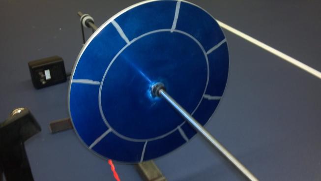
The aluminum rotor with markings to better show its rotation. It rides on a 0.25" shaft supported by pillar bearings.
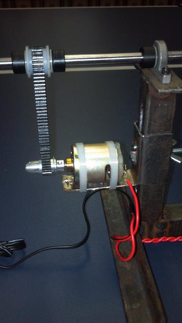
9.6V DC motor with drive belt and clutch bearing on the rotor shaft.
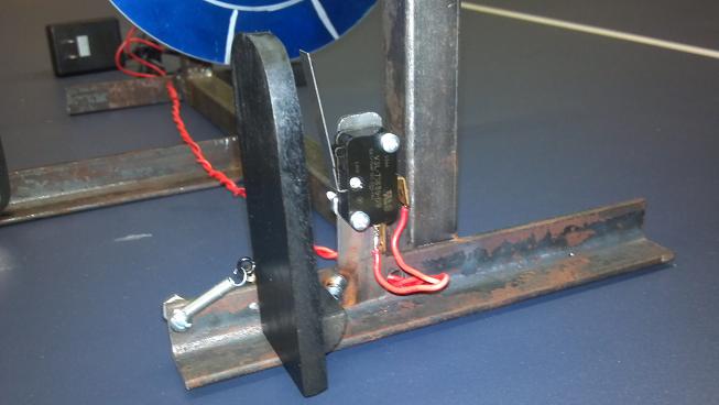
Accelerator pedal featuring return spring and motor power switch.
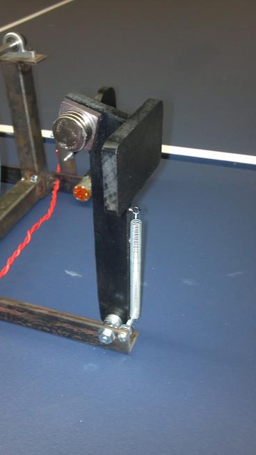
Brake pedal showing the return spring, travel stop, and rare earth magnets.
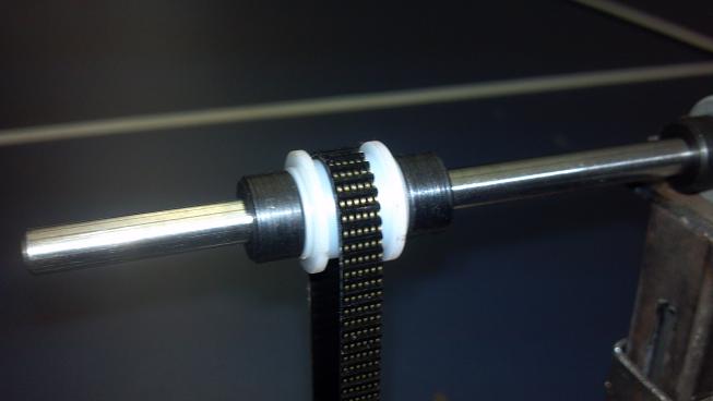
Close up of the clutch bearing. This was needed so that once power was removed from the motor no unwanted drag would be placed on the rotor shaft.

120V AC to 9V DC power source used to drive the motor.