Pulse-Width Modulation (PWM)
by Oleg Sivov, Clemson Electrical Engineering Student
- Basic Description
-
Pulse-width modulation (PWM), also known as pulse-duration modulation (PDM), is a very efficient way of providing intermediate amounts of electrical power to electrical devices, between fully on and fully off. PWM is commonly used as a digital power switch, which provides full power when switched on and no power when switched off. By varying the duty cycle (or the ratio of the on-time to the period), any intermediate amount of power delivered to a device can be achieved. There are many applications of PWM in electronics and other systems, which use PWM to control the speed of a motor, the brightness of light, or to produce an analog signal. Some of the automotive applications include throttle control, fuel ejector control, fuel pump, dome light, interior/exterior lighting, gauges and meters, dc motors, radio volume and others.
Analog Control:
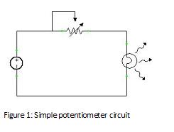
In the older days, before the application of the PWM was made practical with the modern electronic power switches, analog circuits was the way to go about controlling the brightness of a light, the volume of a radio, or the speed of a dc motor. Figure 1 below shows how this was implemented with a simple potentiometer circuit. In an analog radio or the dimming of lights, the knob would usually be connected to the variable resistor. As the knob is turned, the resistance would go up or down. This in turn would limit the amount of current going to the device, and therefore control the brightness of the light. However, this simple analog circuit is not economically attractive and not very practical due to the fact that the analog circuit can get very hot, as a result of undesirable power dissipation in the variable resister, and also that the analog circuit can be sensitive to noise.
Digital Control:
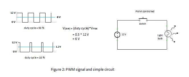
With today's modern technology controlling the amount of power delivered to the device without incurring the losses that would result from power dissipation in a variable resistor can now be implemented digitally. Figure 2 below shows how this can be done. Almost no power is dissipated by the modern switches in either "on" or "off" state. This occurs because when the switch is off, almost no current leaks through the switch, and when the switch is on, the switch has very little voltage drop across its terminals. Only, during the transitions, however, the switch dissipates some power. Modern semiconductors switches such as MOSFETS and Insulated-gate bipolar transistors (IGBTs) are high efficiency devices that are used to perform these high frequency switching.
Many micro-controllers today include on-chip PWM controllers, which makes it possible to efficiently deliver power to various electrical devices. Thus, PWM has greatly replaced analog control circuits due to the reasons of being very economical, efficient, space saving and have better noise immunity. PWM signal remains digital, (even though it can produce analog signals) and is more easily controlled be electronics as oppose to controlling analog signals directly.
- For More Information
- [1] Pulse-Width Modulation, Wikipedia.
- [2] Duty Cycle, Wikipedia.
- [3] Introduction to Pulse-Width Modulation, Netrino website, Nov. 7, 2011.
- [4] PWM Frequently asked questions, JMC, The Fan Company website.
- [5] Pulse Width Modulation (PWM) Tutorial, Datadog Systems [pdf].
- [6] PWM (Pulse Width Modulation), YouTube, June 1, 2011.
- [7] PWM Tutorial, YouTube, Nov 15, 2008.
- [8] Application of - Pulse Width Modulation (PWM), YouTube, Feb 5, 2010.
|