Stepper Motors
- Basic Description
-
Stepper motors are most commonly found in digital control circuits, process control circuits and in machine tools. They are electromechanical devices that convert electrical pulses into discrete mechanical motion. As the electric pulses are received by the motor, the rotor rotates in discrete steps. The speed of the rotation is directly proportional to the frequency at which the pulses are received.
Stepper motors are popular in digital control circuits, such as robotics, because they are well suited for receiving digital pulses for step control. Each step causes the shaft to rotate a certain number of degrees.
The step angle is the rotation of the output shaft caused by each pulse, measured in degrees.
Since stepper motors can be driven with square waves, they are easily controlled by inexpensive digital circuitry. However, by utilizing power modulation techniques to convert the quadrature square waves into sine and cosine waveforms a virtually infinite step resolution is possible. This is called "micro-stepping", where each discrete change in the sine and cosine levels constitutes one micro-step [9].
Advantages:
- Precise and repeatable positioning
- Quick start/stop
- No brushes or commutators
- Very low rotation speeds are possible.
Disadvantages:
- Not easy to operate at high speeds
- Resonances can occur if not controlled properly.
There are basically three types of stepper motors:
1. Variable Reluctance (VR)
Variable reluctance stepper motors do not use a permanent magnet rotor. Instead, the rotor is made of a ferrous material that tries to align itself with the applied magnetic field (much like a nail or iron filings will rotate to align themselves with magnetic field lines). Variable reluctance motors are used for relatively low-torque applications and are much less common than hybrid stepper motors described below.
2. Permanent Magnet (PM)
Permanent magnet stepper motors use a permanent magnet rotor. The rotor normally has two poles that align themselves with the corresponding poles that are energized on the stator. These motors are relatively inexpensive, but usually have larger step sizes than hybrid stepper motors.
3. Hybrid (HB)
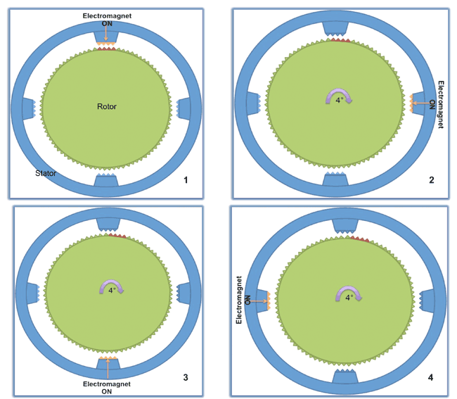
Hybrid motors combine the best characteristics of the variable reluctance and permanent magnet motors. They are constructed with multi-toothed stator poles and a permanent magnet rotor with multiple teeth on each pole. Hybrid motors have teeth on the rotor that are slightly misaligned with teeth on the stator at successive pole positions. When one position on the stator is energized, the rotor rotates one step to align its teeth at that position. Energizing the next pole on the stator causes the rotor to rotate an additional step to align its teeth at the new position. This technique allows the number of steps to be greater than the number of poles on the stator.
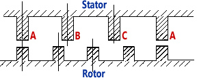
Standard hybrid motors have 200 rotor teeth and rotate at step angles of 1.8 degrees (2 phases), 0.9 degrees (3 phases), or 0.72 degree (5 phases). Because they exhibit high static and dynamic torque and can run at very high step rates, hybrid motors are used in a wide variety of industrial applications.
- Manufacturers
-
Advanced Micro Systems,
Astrosyn,
Continental,
ElectroCraft,
Hansen,
Haydon,
JVL,
Kollmorgen,
MicroMo,
Mitsumi,
Parker,
NMB,
NPM,
Phytron,
Portescap,
Rebek,
Sanyo Denki,
Saehan,
Shinano Kenshi
- For More Information
- [1] Stepper Motor, Wikipedia.
- [2] Stepper Motor Basics (pdf, 200KB), Solarbotics.net.
- [3] Step Motor, YouTube, May 28, 2007.
- [4] How Stepper Motors Work, Images Scientific Instruments web site.
- [5] What is a Hybrid Stepper Motor, YouTube, Feb. 9, 2009.
- [6] Introduction to Stepper Motors and Drives, Omega Engineering Technical Reference.
- [7] Stepper Motor: In Depth, Freescale website.
- [8] Basics of MicroStepping, YouTube, Oct. 7, 2011.
- [9] Types of Stepper Motors (detailed), National Instruments white paper, Sep. 25, 2013.
|