Notes
- The formulas used here are taken from the Design Guide for Electronic Packaging
Utilizing High-Speed Techniques (4th Working Draft, IPC-2251, February 2001)
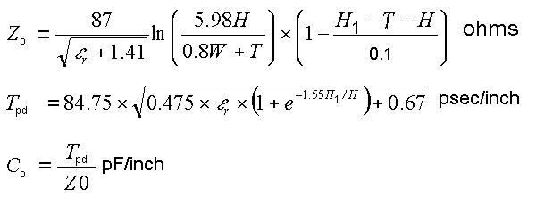
- Range of valid parameters specified in the Design Guide: 0.1< W/H
< 3.0; 1 < εr < 15
- Note the equations used here are proposal currently being evaluated by IPC.
The embedded microstrip impedance formula is an approximation and the results
are highly sensitive to the values of the variables. The accuracy of the equations
was observed to be slightly better for higher permittivities.
- For typical PCB parameters (εr
= 4, H1 = 61.37 mil, H = 30 mil and T = 1.37 mil), the
deviation of the calculated results obtained using a 2D numerical field solver, is listed below:
| Z0: |
|
| 0.1 < W/H < 1.0 |
within 20% |
| 1.0 < W/H < 3.0 |
20%--40% |
| C0: |
|
| 0.1 < W/H < 1.0 |
within 5% |
| 1.0 < W/H < 2.2 |
within 20% |
| 2.2 < W/H < 3.0 |
20%--40% |
|