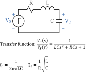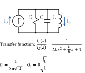
Step Response of an RLC Circuit
by Dexin Zhang, Clemson Automotive Engineering Graduate Student
This calculator computes the resonant frequency and corresponding Q factor of an RLC circuit with series or parallel topologies. The resonant frequency here is defined as the frequency at which the amplitude of the impedance or the admittance of the circuit has a minimum. The Q factor here is defined as 2π times maximum energy stored over energy dissipated per cycle at the resonant frequency. In addition to the calculation, unit step response of the voltage VC across the capacitor for the series circuit, or the current IL through the inductor for the parallel circuit is plotted.
|
|
||||
| series | parallel |
 |
||
| R: | Ω | |||
| L: | nH | |||
| C: | nF | |||
|
|
||||
| fr: | MHz | Resonant frequency | ||
| Qf: | Q factor | |||
