Common-Mode EMI Calculator | |
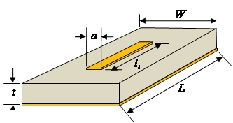
The fields that couple from a circuit board trace directly to cables attached to the circuit board can induce common-mode currents on these cables resulting in radiated emissions. Electric-field coupling is proportional to the magnitude of the voltage on the trace. Magnetic field coupling is proportional to the current flowing in the trace. For a given board geometry, a closed-form expression for the maximum emissions due to these coupling mechanisms is described in [1, 2].
| |
Side View | Top View |
 |
|
|
Important Note: This algorithm was revised in January 2014. The new algorithm does not ask for the source impedance. The voltage input by the user is the signal voltage, not the open-circuit source voltage. The signal current is the signal voltage divided by the load impedance. The new algorithm is described in [3]. [1] C. Su and T. Hubing, "Improvements to a Method for Estimating the Maximum Radiated Emissions From PCBs With Cables," IEEE Trans. on Electromagnetic Compatibility, vol. 53, no. 4, Nov. 2011, pp. 1087-1091. [2] C. Su and T. Hubing, "Imbalance Difference Model for Common-Mode Radiation from Printed Circuit Boards," IEEE Trans. on Electromagnetic Compatibility, vol. 53, no. 1, Feb. 2011, pp. 150-156. [3] C. Zhu and T. Hubing, "Maximum Radiated Emission Calculator: Common-Mode EMI Algorithm," CVEL-13-051, Dec. 23, 2013. | |
← Return to MR EMC | |