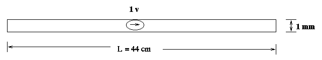
The center-fed flat dipole in Figure 7 has a width of one millimeter and a length of 44 centimeters. It is fed by a 300-MHz voltage source with a magnitude of one volt. The input file for SIFT5 is as follows:
# example 1: a flat dipole antenna driven by a voltage source in the middle
unit 0.5 mm
conductor 0 0 2 880 2 2 10 1 1
vsource 440 0 2 440 2 2 300 x 1.0
output 0 0 2 840 2 2 y example1.out
The structure is divided into 268 triangles. The total number of unknown edges is 438.
A flat dipole antenna can be treated as a cylindrical dipole antenna with an equivalent radius a=0.25w, where w is the width of the flat dipole antenna [1]. If a < L/100, where L is the length of the dipole, the input impedance of t he cylindrical dipole is given by [1]:
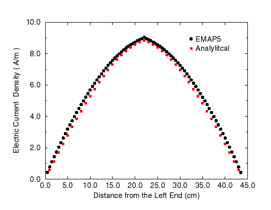
where k is the wavenumber, a is the wire radius. Si(x) and Ci(x) are the sine and cosine integral functions, and C=0.5772 (Euler's constant). Figure 8 shows the current distribution along the flat dipole calculated by EMAP5 and the theoretical current distribution on an equivalent cylindrical dipole.
The output of EMAP5 is the surface electric current J along the flat dipole. The current at the source is given by:
I = Jf * w
where Jf is a complex number denoting the surface current across the source edge, and w is the width of the edge. In this example, two edges are used to model the source. Thus, the total current is the sum of currents across the two edges.
The input impedance of the dipole is given by:

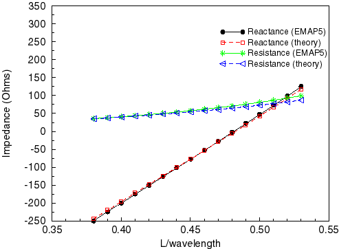
Figure 9 shows the input resistance, input reactance and impedance obtained by EMAP5 as the dipole length is adjusted from 38-53 cm, with a comparison of analytical results. Good agreement between EMAP5 and the theoretical results is achieved.
References:
[1] Constantine A. Balanis, Antenna Theory Analysis and Design, 2nd Edition, New York: John Wiley & Sons Inc, 1997.