
The Standard Input File (SIF) FormatThe Standard Input File (SIF) Format was developed with three primary objectives:
Each line of the input file is either a data line or a comment (blank lines are ignored). Comment lines begin with a # sign and may be ignored or copied to the output file by the modeling code. All data lines consist of a keyword followed by space-delimited parameters. The format and the number of parameters depends on the keyword. For example, the line dielectric 1 1 1 8 2 8 4.2 .002 1.0 d contains the keyword "dielectric". This keyword must always be followed by at least 8 parameters. The first 6 parameters of the dielectric keyword define the shape and position of the dielectric. The next 2 parameters define the relative permittivity and conductivity of the dielectric. The ninth parameter is optional and defines the relative permeability. The last parameter, also optional, is a character that, in this case tells the mesh generator to use an extra fine mesh in this region of the geometry. A number of keywords have been defined, some of which are briefly described in the table below: |
boundary        x1      y1      z1      x2      y2      z2                              - surface of a meshed volume
box             x1      y1      z1      x2      y2      z2                              - hollow pec surface
conductor       x1      y1      z1      x2      y2      z2     rad   seg#  ntag         - pec volume, surface, or wire
aperture        x1      y1      z1      x2      y2      z2     name                     - hole in pec
dielectric      x1      y1      z1      x2      y2      z2     eps   sig   mu    m1     - dielectric region
esource x1      y1      z1      x2      y2      z2      freq   dir   mag   ph           - electric field source
msource x1      y1      z1      x2      y2      z2      freq   dir   mag   ph           - magnetic field source
vsource x1      y1      z1      x2      y2      z2      freq   dir   mag   ph           - voltage source
isource x1      y1      z1      x2      y2      z2      freq   dir   mag   ph           - current source
gndplane        orient  value                                                           - ground plane
iterate         x1      y1      z1      x2      y2      z2      p1                      - repeat geometry
Execution Keywords
celldim         value   units                                                           - mesh units
execute         p1                                                                      - run program (y or n)
Output Keywords
efield_output   x1      y1      z1      x2      y2      z2  out_filename                - evaluate electric field
hfield_output   x1      y1      z1      x2      y2      z2  out_filename                - evaluate magnetic field
pplot           distance        a-init  a-delta out_filename                                        - generate polar plot data
default_output  out_filename                                                            - generate default output
|
Note that in addition to geometry keywords, there are keywords that affect the execution of the program and keywords that determine the output parameters. Not all EM modeling codes will take advantage of every keyword. For example, the EMAP codes ignore any boundary statements in their input files, since unconstrained boundaries are not permitted. There were 8 keywords that were recognized and used by the EMAP version 2.0 codes. EM modeling codes should be written to accept all valid keywords, but warn the user if any keywords in the input file are being ignored. The basic keywords described in above and their parameters have been chosen so that they are meaningful to EM codes based on a variety of EM modeling techniques. Codes that employ surface grids, codes with fixed volume meshes, and codes that require mesh generators, can all read the same input file and interpret it in a similar manner. Codes based on the finite element method, the FDTD method, and a hybrid FEM/MOM technique have all been adapted to read SIF files. Examples
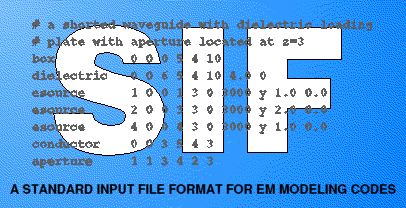
The input file corresponding to a dielectric-loaded waveguide is shown in the figure above. The waveguide is driven at one end with an electric field and shorted at the other end. An IGES standard format description of this geometry is 195 lines long and does not include the source information. The input file above, on the other hand, is 5 lines long and contains all the information required by the EM modeling code.
The figure above shows the input file corresponding to a very simple printed circuit board configuration. The IGES format description requires 159 lines without the source. The input file above is 15 lines. Both of the SIF files in these examples were generated with a simple text editor and are intuitive enough to visualize without a graphical user interface. Applications of SIFThe SIF input file format can potentially be used with a variety of EM modeling codes. By establishing a standard input file format, code developers are isolated from user interface issues and they are free to develop codes that are relatively platform independent. Code users also benefit from a standard input format because they are able to choose a single compatible user-interface and use it with a variety of EM modeling codes. So far, this input format is being used with three different EM modeling codes. One is a finite element code, one is an FDTD code, and the other is a hybrid code. Although a CAD interface that employs this input format has been developed, the authors typically find that simply creating the input files using a text editor is quicker and simpler. Development of the SIF format is still under way. Enhancements continue to be made as the authors gain experience using the new input format and as they receive suggestions from code users. Reference[1] T. H. Hubing, C. Hong-Him Lim and J. Drewniak, "A Geometry Description Language for 3D Electromagnetic Analysis Codes," Proceedings of the 10th Annual Review of Progress in Applied Computational Electromagnetics, Monterey, CA, March 1994, pp. 417-422. |
