Modeling a Center-Driven Dipole with CST
|
Geometry and setup |
Geometry: L= 1 m,
a = 0.5 mm
Model parameters:
- Frequency: 50 MHz ~ 400 MHz
- Steady state accuracy limit: -60 dB
Mesh
definition:
- Mesh type: Hexahedral
- Mesh density control: Lines per wavelength = 30,
Others = Default
- Special mesh properties:
Refine at PEC/lossy metal edges by factor = 6,
Others = Default
- Automesh
Excitation: Discrete port
(1 W, 50 ohms)
 cst_dipole.zip cst_dipole.zip
|
|
Simulation result |
Simulation time: 12 secs
Number of mesh cells: 3600
Excitation duration: 2.031171e+001 ns
Calculation time for excitation: 4 secs
Number of calculated pulse widths: 3.49899
Simulated number of time steps: 8988
Maximum number of time steps: 51374
|
|
Decisions the user must make that affect the
accuracy of the result |
- Mesh density control: the minimum Lines per wavelength is 30.
- Special mesh properties: 6 or greater value is needed for 'Refine at PEC/lossy metal edges by factor'
to obtain higher accuracy.
|
|
Comments |
- Adding the source requires a gap between the two wires. What
is the source gap length?
In this model, the interval
between two antenna parts is 1 mm.
- What if we model the dipole as a flat ribbon?
Substituting a 2-mm
flat ribbon for a 0.5-mm radius round wire is not allowed in this model.
| |
|
Screen shots
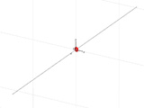
Fig. 1. Simulation model
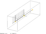
Fig. 2. Simulation meshes
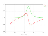
Fig. 3. Input impedance
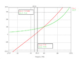
Fig. 4. Input impedance at the first
resonant
frequency | |
)
)
)
)