Modeling a Powerbus with EMAP
Geometry and setup |
Double-sided PCB:
- Size: 125 mm × 100 mm × 1 mm
- Top and bottom metal: PEC
- Dielectric: FR4, εr = 4.5, dielectric loss tangent = 0.015
Excitation: Current source (0.02 A, 50 ohms)
Mesh Setup:
- Dielectric mesh size: 1 mm × 8 mm
- PEC mesh size: 8 mm × 8 mm
Frequency: 5 MHz - 2 GHz, Step Size = 5 MHz
|
Simulation result |
Simulation Time: 22 hrs
Number of triangles: 952
Number of tetrahedra: 2390
Number of edges: 3560
|
Decisions the user must make that affect the accuracy of the result |
- Thickness of dielectric: 1 mm
- Number of triangles and tetrahedra: We used a commercial mesh generator that created 952 triangles and 2390 tetrahedra.
- Aspect ratio of triangles and tetrahedra: less than 5
|
Comments |
- How is a powerbus modeled in EMAP?
In EMAP the powerbus is modeled as a slab of dielectric with two
PEC sheets attached to the top and bottom surfaces of the slab. The relative permittivity
and the loss tangent of the dielectric are assigned in the input file.
- What kind of source can be used for a powerbus in EMAP and how is it placed?
For the Powerbus model, a current source can be applied in the dielectric on
one inner edge connecting the two metal sheets. A resistive load can be assigned to the same edge of
the source and serves as the source resistance.
- What kind of mesh is used for the powerbus in EMAP?
In EMAP, all the external or surface metal is meshed as triangles. The density and
aspect ratio can be controlled with the meshing software. The dielectric part is meshed
as tetrahedra. At the interface where the surface metal joins the faces of the tetrahedra,
the surface metal triangles exactly overlap with the tetrahedra faces. This was accomplished
using commercial meshing software.
- What simulation methods are used for the powerbus in EMAP?
This model has metal, dielectrics, and calculates far-field radiation. The Method of Moments (MOM)
part of the code is used for the metal triangles; and the Finite Element Method (FEM) part is used for the
dielectric. The EMAP code couples these parts at the interface. In this case, the interface was defined
to be the surface of the dielectric slab.
|
|
|
Screen shots
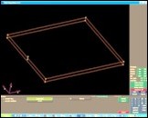
Fig. 1. Simulation model
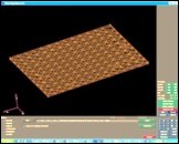
Fig. 2. Simulation meshes
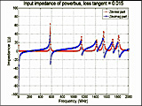
Fig. 3. Input impedance
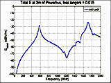
Fig. 4. Electric field at 3 m, θ=0°, φ=0°
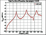
Fig. 5. Electric field at 3 m, θ=90°, φ=0°
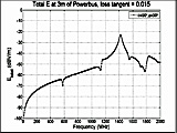
Fig. 6. Electric field at 3 m, θ=90°, φ=90°
|
|
)
)
)
)
)
)