Modeling a Center-driven Dipole with FEKO
|
Geometry and setup |
Geometry: L= 1 m,
a = 0.5 mm
Mesh:
- Global mesh size: Edge length=40 mm, Segment
length=0.2 mm, wire radius=0.01 mm
- Disable volume meshing
- Small features: default
- Advanced: Enable mesh smoothing
Solution
- Frequency: Linearly spaced discrete points:50
MHz - 400 MHz, number of frequencies = 71
- Excitations: Voltage source (1 V, 50 ohms)
 feko_dipole.zip feko_dipole.zip
|
|
Simulation result |
Simulation Time: 1
min 13 secs
Number of metallic triangles: 328
Number of metallic edges (MOM): 3
Number of basis functions (MOM): 496
|
|
Decisions the user must make that affect the
accuracy of the result |
- The segment length should be smaller than a tenth of the free
space wavelength.
- Segments should not be too short relative to the wire radius.
Ideally, the segment length should be at least four times the
radius.
- For MOM mesh elements, the side length of triangles should be
shorter than approximately λ/5. If the memory constraints allow
it, an edge length less than λ/10 is preferred. In this case, the
edge length is λ/50.
|
|
Comments |
- Adding the source requires a gap between the two cylinders.
What is the source gap length?
In this model, the interval
between two antenna parts is 0.4 mm.
- What meshing rules should be adhered to in this model?
In FEKO, a segment is defined as a short section of wire
(short in comparison with the wavelength). In this model, the
voltage source is implemented using a short wire which connects
the upper and the lower part of the antenna. Since the segment
current flows only in the axial direction, the segments should not
too short relative to the wire radius. Ideally, the segment length
should be at least four times the radius. In this model, the wire
radius is 0.01 mm. The "segment length" field in the Create Mesh
dialog is set to 0.2.
Another meshing guideline in FEKO is to
ensure that the edge length of surface mesh elements is less than
λ\10. This half-wave dipole resonates at about 150 MHz
corresponding to a wavelength of about 2 m. In this model, the
edge length is about λ/50.
- How can we simplify the round wire model?
Using the equivalent radius
concept, a round wire antenna can be approximated by a planar strip, or flat ribbon. The equivalent
width of the ribbon is 4 times the round wire radius. Furthermore, since the radius of the dipole is much
smaller than its length, the dipole can be also modeled as a vanishingly thin wire. Both the flat ribbon
and the wire model significantly reduce the simulation time.
More
information... | |
|
Screen shots
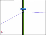
Fig. 1. Simulation model
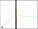
Fig. 2. Simulation meshes
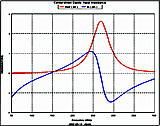
Fig. 3. Input impedance
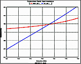
Fig. 4. Input impedance at the first
resonant
frequency | |
)
)
)
)