Modeling Powerbus and Cable with FEKO
|
Geometry and setup |
Double-sided PCB:
- Size: 125 mm × 100 mm × 1 mm
- Top and bottom metal: PEC
- Dielectric: FR4, εr = 4.5, dielectric loss tangent = 0.015
Cable (wire):
- Length: 1000 mm
- Wire radius: 0.01 mm
- Material: PEC
Mesh:
- Global mesh size: Edge length=6 mm, Segment length=0.5 mm, wire radius=0.01 mm
- Disable volume meshing
- Small features: default
- Advanced: Enable mesh smoothing
Solution
- Settings: Double precision
- Frequency: continuous (interpolated) range:5 MHz - 2 GHz, maximum number of samples=200
- Excitations: Voltage source (1 V, 50 ohms)
- Calculation: Far field, θ=0° - 90°, φ=0° - 90°
 feko_powerbus_cable.zip feko_powerbus_cable.zip
|
|
Simulation result |
Simulation Time: 6 hrs
Number of metallic triangles: 2214
Number of dielectric triangles: 206
Number of metallic edges(MOM): 6394
Number of basis function for MOM: 9013
|
|
Decisions the user must make that affect the
accuracy of the result |
- Uncheck the 'Enable volume meshing'. For the power bus problem, the results with MOM will be accurate
|
|
Comments |
- How do we define the infinite ground plane?
Select Solution, then double-click Infinite planes under Solution
in the tree to open the Infinite planes dialog. Check the second item: Ground plane.
- Can a port be located at the edge of the surface?
In this model, the source port cannot be located on the dielectric surface.
A connection was created 0.5 mm away from the edge of the board.
- Can we model the 2-m cable using the wire model?
Yes. One side of the wire connects to the middle point of the edge port.
The other side of the wire touches the infinite ground plane. The wire radius is 0.01 mm.
| |
|
Screen shots
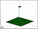
Fig. 1. Simulation model
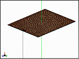
Fig. 2. Simulation meshes
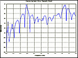
Fig. 3. Electric field at 10 m,
θ=0°, φ=0°
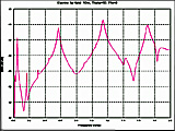
Fig. 4. Electric field at 10 m,
θ=90°, φ=0°
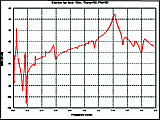
Fig. 5. Electric field at 10 m,
θ=90°,
φ=90° | |