|
Evaluation of Electromagnetic Modeling Tools, May 2007
Can we use the "wire model" feature to represent the dipole? Modeling the Center-Driven Dipole with Microstripes Modeling the dipole as a "wire" rather than as a "cylinder" greatly improved the simulation time. The wire model is shown in Figure 4. A wire port is applied in the middle of the wire to produce the voltage source. The results are shown in Figures 5 - 7. Two successive peaks near the resonant frequency were obtained when the default settings were used (except the extent was set to 40%), as shown in Figure 5. When the maximum cell size was set to default/4, and the minimum cell size was maximum/40, the results shown in Figure 6 were obtained. The resonant frequency is 147 MHz, the impedance at 150 MHz is 76.6+j24.1 ohms. The simulation time was only 5 minutes. The comparison of the results between the cylinder model and wire model with finer mesh settings is shown in Figure 7. 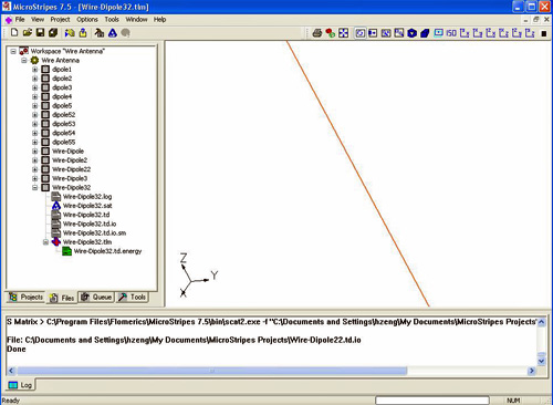
Fig. 4. Wire model
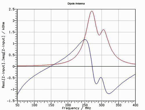
Fig. 5. Wire model results with default settings
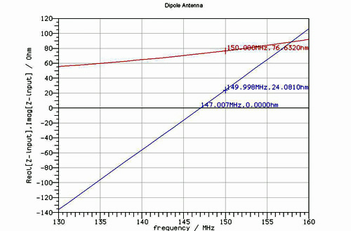
Fig. 6. Wire model results with finer mesh settings.
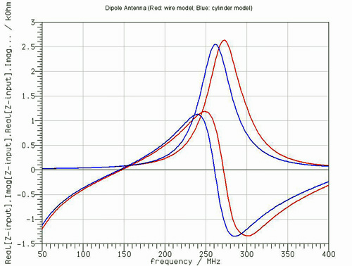
Fig. 7. Comparison between wire model and cylinder model
|