Can MicroStripes model dielectric materials with constant loss tangent?
Modeling the Powerbus and Cable with Microstripes
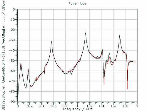
In MicroStripes, we cannot set a constant loss tangent for a dielectric. Figure 4 shows the electric field at (10 m, 90 degrees, 0 degrees) when we input the conductivity corresponding to a given loss tangent at different frequency points of interest. The black line represents the lossless dielectric. The green line represents a loss tangent of 0.015 at 567MHz. The blue line represents a loss tangent of 0.015 at 1.136GHz. The red line represents a loss tangent of 0.015 at 1.708GHz. These results can be compared to results obtained using the EMAP and HFSS codes on this web site.