|
Evaluation of Electromagnetic Modeling Tools, January 2009
Modeling the Dipole as a Round Wire or Flat Ribbon Modeling a Center-driven Dipole with HFSS The round wire can be approximated by a narrow, flat ribbon. The flat ribbon has the same length, zero thickness, and an equivalent width. The relationship between the equivalent width w of the flat ribbon and the radius a of a round wire is derived by assuming that the surface current density is uniformly distributed on the effective surface of the two dipole arms [1]. w = 4 ×a The input impedance of a 0.5-m long dipole was calculated using these two models. The results are plotted in Figure 1.
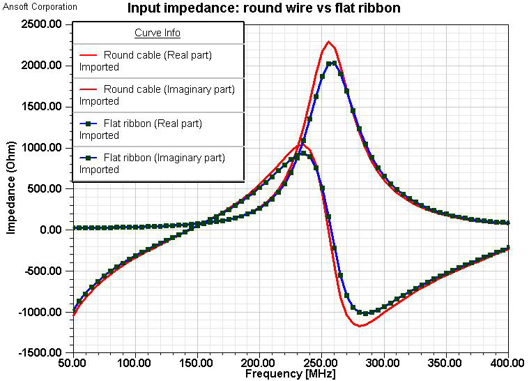
Fig. 1. Input impedances of round wire and flat ribbon models
The input impedances of the two models, 0.5-mm round wire and 2-mm wide flat ribbon, are almost the same over the frequency range evaluated. Also, we compared the results in the following table.
Depending on the radius of the wire, the length of the dipole for the first resonance is about L = 0.47 to 0.48 wavelengths [1]. For a 1-m dipole, the first resonance frequency should be between 141 MHz and 144 MHz. Using the flat ribbon model, both the input impedance and the resonance frequency are close to the theoretical values. Reference: [1] C. Balanis, Antenna Theory: Analysis and Design, pp. 403-412, pp. 449-453, John Wiley & Sons, Inc., New York, 2001. | |||||||||||||||||||||