| Evaluation of Electromagnetic Modeling Tools, January 2009
Radiation boundary and infinite ground plane Modeling the Powerbus and Cable with HFSS To simulate the effects of an infinite ground plane, a lossless ground plane was approximated by selecting the infinite ground plane check box when assigning a perfect E boundary. By default, all HFSS model surfaces exposed to the background are assumed to have perfect E boundaries. Hence, it is straightforward to use the bottom face of the radiation cylinder as the infinite ground plane.
In HFSS, a radiation surface must be at least a quarter wave-length
from the radiating source.
In this simulation, the first resonant frequency appears at about 50 MHz. To capture this
resonant point, the radiation boundary must be at least a quarter wavelength (6 m for 50 MHz)
away from the circuit board. Two sizes of radiation boundaries were evaluated and compared.
The results are shown in Figures 1 - 4. It is clear that when the
boundary is within a quarter wavelength of the object, the peak values of the far field radiation at resonant frequencies are inaccurate. 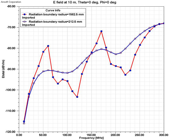
Fig. 1. Electric fields from different meshes, θ=0°, φ=0°
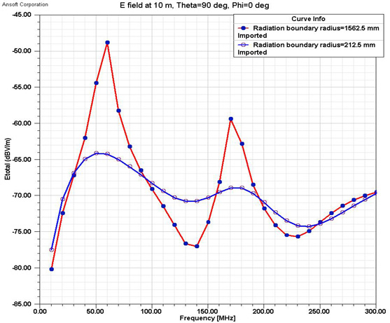
Fig. 2. Electric fields from different meshes, θ=90°, φ=0°
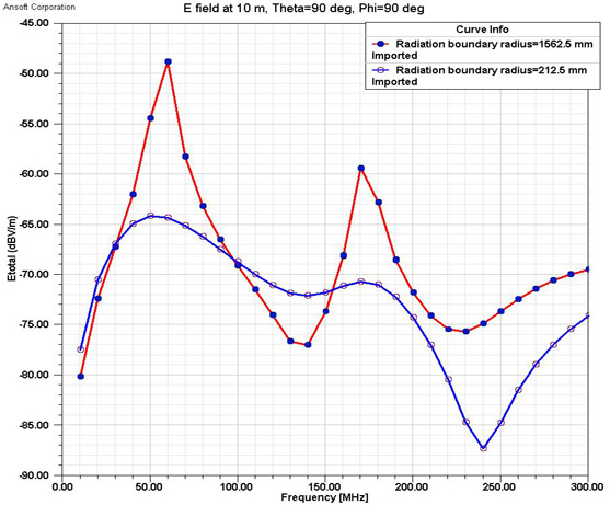
Fig. 3. Electric fields from different meshes, θ=90°, φ=90°
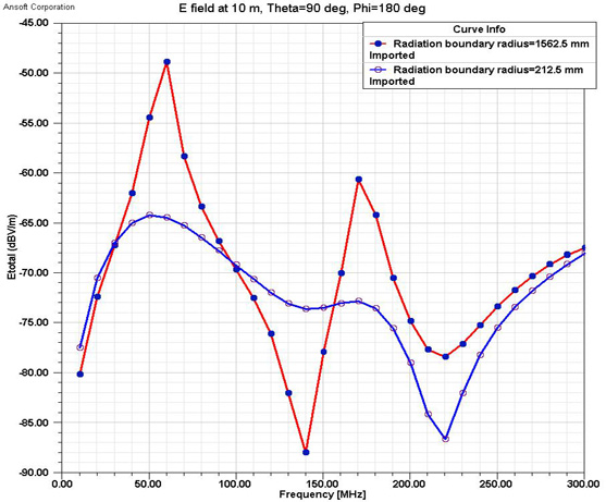
Fig. 4. Electric fields from different meshes, θ=90°, φ=180°
In this simulation, the wavelength varies over a wide range. It is not easy to select a boundary size that produces accurate results at both the low and high frequencies. A good solution is to divide the frequency range into two parts, a low frequency part (10 MHz - 300 MHz) and a high frequency part (300 MHz - 2 GHz). Different radiation boundaries are used for each part. |