Modeling Parallel Plate Capacitor with LCGEN
Geometry and setup |
Plate size: 200 mm × 200 mm × 0.1 mm
Gap between the two plates: 10 mm
Setup:
The structure was drawn using the model editor.
Then, using the simulation file builder, the model file was opened and the
simulation default parameters were utilized. The build file and run option
was then selected.
 ibm_parallelplates.zip
|
Simulation result |
Capacitance: 39.007 pF
|
Model decisions |
- Materials
- Copper modeled as a PEC
- Dielectric was air
- Simulation
- Output charge data selected to obtain a graphical representation
- Disabled inductance solution because it won't work with this setup
- Ran simulation in the foreground
|
Comments |
- How intuitive is the interface for LCGEN?"
The interface for LCGEN is easy to learn, though a little clumsy to use.
There aren't a lot of options included with this software, just what you need to model simple geometries.
- What is the drawing interface like?
The drawing interface allows a user to input the min/max vertices of each shape.
There are several included shapes that it will automatically draw, but they are not intuitive to a new user.
For someone with a lot of CAD experience this interface should be quick to learn. For people without
that experience it can be time consuming learning how to convert a geometry into a list of min/max points.
- Would the capacitance be different if you modeled this configuration with zero-thickness plates?
There is a small change in the results due to the change in the electric field distribution at the
edges of the plates.
|
|
Screen shots
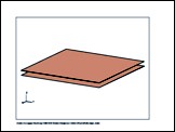
Fig. 1. Simulation model
|
|
)