|
Evaluation of Electromagnetic Modeling Tools, October 2009
Other Ways to Model the Dipole Antenna Modeling a Center-driven Dipole with IE3D In this example, we can model the thin wire as a metallic strip, a rectangular tube or a tube with more sides. Using the "build wire path" command in MGRID, a round wire can be approximated by different geometry structures. By setting the number of segments for the circle to 6, the wire antenna is built with a cylindrical tube that has a hexagonal cross-section. If the number of segments for the circle is 4, the wire is built with a rectangle tube. If we set the number to 2, the wire antenna is built with a flat strip. Comparing the 3 cases, the results for the hexagonal cross-section, the rectangular tube and the flat strip are shown in Figure 1. 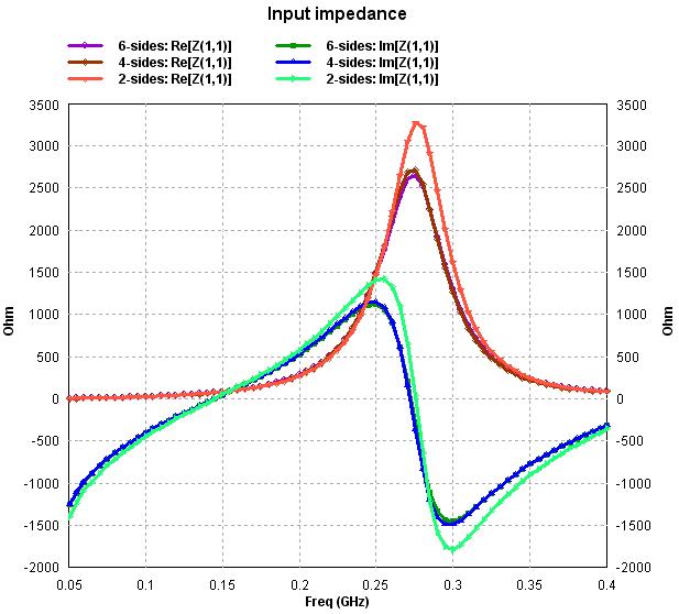
Fig. 1. Input impedances of tube with 6 sides, rectanglular tube, and flat ribbon models
The input impedances of the three models are very close over the frequency range evaluated. These results are shown in the following table.
The differences among the three models are quite small. Reference: [1] IE3D User's Manual, release 14.1, Zeland Software, Inc., May 2008. | ||||||||||||||||||||||||||||