Modeling a Powerbus and Cable with IE3D
|
Geometry and setup |
Double-sided PCB:
- Size: 125 mm × 100 mm × 1 mm
- Top and bottom metal: PEC
- Dielectric: FR4, εr = 4.5,
dielectric loss tangent = 0.015
Cable (round cable):
- Length: 1000 mm
- Radius: 1 mm
- Material: PEC
Simulation Setup:
- Meshing parameters: meshing frequency = 2 GHz, cells/wavelength = 18
- Mesh alignment is enabled: Align polygons and dielectrics
- Adaptive Intelli-Fit (AIF): disabled
- Matrix solver: default SVSa
- Frequency Parameters: 10 MHz - 2 GHz, Step Size = 10 MHz
- Excitation: Voltage source (1 V, 50 ohms)
 ie3d_powerbus_cable.zip ie3d_powerbus_cable.zip
|
|
Simulation result |
Simulation Time: 5698 seconds
Number of Cells/Volumes/Unknowns: 543/201/1716 |
|
Decisions the user must make that affect the
accuracy of the result |
- Define the dielectric block as a finite substrate: By default, the substrate size is infinitely large in IE3D.
In this case, the dielectric block should be defined as a finite substrate. Please refer to the comments for
details.
- Align meshing between the polygons and the finite dielectric: The reason is that meshing alignment between
the finite dielectrics and the patch is extremely critical to the simulation results.
- Define a port as a pair of positive and negative terminals: When there is no infinite ground plane, a user
needs to define a port as a pair of positive and negative terminals. Numerical error may be introduced if we
don't define a port in pair (+, -) or define a differential port (vertical localized or horizontal localized
port with self-contained + and - terminals) on a structure without an infinite ground plane.
- Make sure the cable is electrically connected to the board and the infinite ground plane
|
|
Comments |
- In case we need to build a structure with many polygons
with some of them connected and some of them
not connected, how can we guarantee the "electrical connection" between them?
In the IE3D, two polygons are considered to be connected only when they have a common edge with two matching
vertices. Otherwise, they will be considered as disconnected even if they look as if they are connected. Polygon
connection or "electrical connection" is a very important concept in the IE3D.
There are two ways to know whether two polygons are connected or not. First, if they are connected,
there are some red dots on the common edge of the two polygons. These red dots are used to denote
that the polygons are connected on the common edge. Second, the "Check connection command" will highlight
the other polygons which are electrically connected to the selected polygon.
- What is the difference between the IE3D results and the results from the other codes?
There are some unknown peaks in the radiated electric field plots. They are not shown in the results from the other codes.
The origination of these peaks is unclear and requires further investigation.
| |
Screen shots
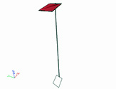
Fig. 1. Simulation model
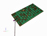
Fig. 2. Simulation meshes
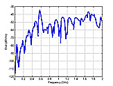
Fig. 3. Electric field at 3 m,
θ=0°, φ=0°
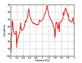
Fig. 4. Electric field at 3 m,
θ=90°, φ=0°
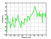
Fig. 5. Electric field at 3 m,
θ=90°,
φ=90° | |
)
)
)
)
)