Modeling the Capacitance of an SMT Capacitor with Q3D
Geometry and setup |
Pad size: 0.5 mm × 0.5 mm × 0.017 mm
Cathode/Anode: 0.5 mm × 0.1 mm × 0.5 mm
Plate: 0.5 mm × 0.7 mm × 0.05 mm
Dielectric: 1.5 mm × 1.8 mm × 0.1 mm
Gap between any two plates: 0.1 mm
Capacitor size: 1005
Dielectric: εr = 4.4
Solve Setup:
Solver residual: 0.0001
Adaptive solution:
- Maximum number of passes: 10
- Minimum number of passes: 1
- Minimum converged passes: 1
- Percent error: 1%
- Percent refinement per pass: 30%
 q3d_smtcap.zip
 |
Simulation result |
Anode Capacitance: 0.521 pF
Cathode Capacitance: 0.524 pF
Mutual Capacitance: 0.495 pF
|
Decisions the user must make that affect the accuracy of the result |
- Solver residual : 1e-005
- Percent error for adaptive solution: 1%
- Dielectric constant of the capacitor
- Distance between two electrodes
|
Comments |
- The distance between plates is much larger than we would find in an actual SMT Multi-Layer Capacitor (MLC).
Why not model a more realistic geometry?
The complexity of a real SMT MLC would require significantly greater computer resources
to model accurately and the solution would be sensitive to details in the problem geometry and in
the mesh geometry. While a great deal can be learned about the factors affecting the capacitance
of an SMT MLC from these models, it is not likely that two different codes would yield identical
results.
|
|
Screen shots
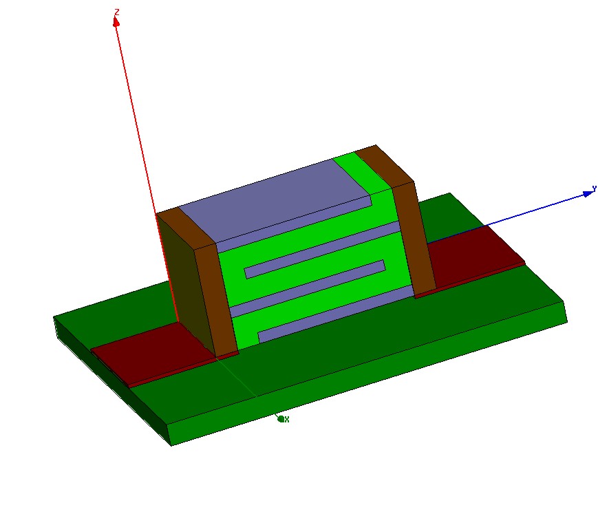
Fig. 1. Simulation model
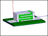
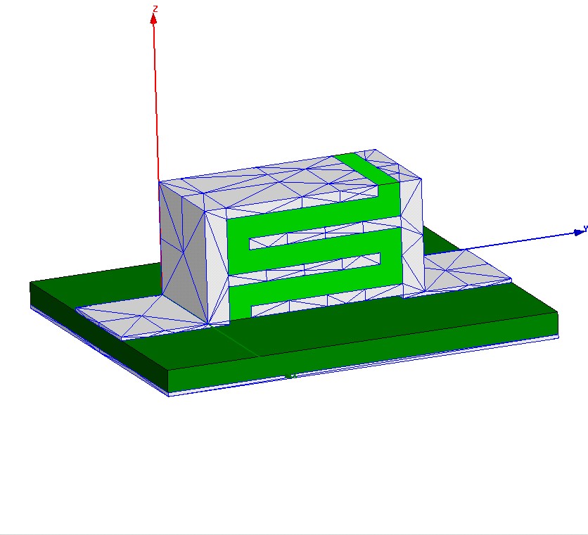
Fig. 2. Simulation meshes
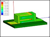
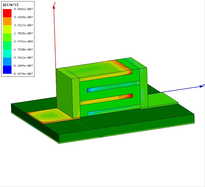
Fig. 3. Charge density
|
|