Exhaust Energy Recovery Systems
by Shri Aditya Varanasi, Clemson Automotive Engineering Graduate Student
- Basic Description
-
In an effort to reduce fuel consumption in Formula One racing, the FIA (Federation Internationale L"Automobile) has introduced wholesale changes to the technical regulations that significantly increase energy harvesting for the 2014 season. Earlier, Kinetic Energy Recovery Systems (KERS) were used to store energy only when the vehicle was braking and return it when accelerating. Now, the FIA has also mandated Exhaust Energy Recovery Systems (EERS) along with kinetic energy recovery. The new system is called the Energy Recovery System (ERS). The ERS has two main recovery devices, the Motor Generator Unit-Kinetic (MGU-K) and the Motor Generator Unit-Heat (MGU-H). The latter uses heat energy from the turbo to generate electrical energy. ERS kinetic energy recovery is a more advanced version of KERS. Not only does it still harvest energy from and deploy energy to the rear axle, it also does the same from the turbocharger.
Motor Generator Unit - Kinetic
The MGU-K is connected to the crankshaft of the internal combustion engine and is capable of recovering or providing power. Under braking, the MGU-K operates as a generator to slow the car (reducing the heat dissipated in the brakes) and so recovers some of the kinetic energy and converts it to electricity. Under acceleration, the MGU-K is powered and acts as a motor to help propel the car.
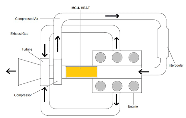
Motor Generator Unit - Heat
MGU-H is a combination of turbo charger and generator. The MGU-H unit captures waste heat as it is dispelled from the exhaust turbocharger via an electric generator attached to the turbocharger shaft. This waste heat energy is stored as an electrical charge. At low revolution speeds, when the engine exhaust power is low, the generator functions as a motor that powers the revolution of the turbocharger. As soon as the turbocharger revolution speed is high enough, the generator produces electricity for charging the battery bank of the drive assist system. Because this allows the combination of even higher fuel efficiency with high output power, the concept is garnering worldwide attention and may come to represent a new racing engine generation.
Energy Recovery System
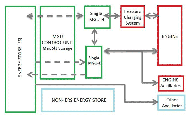
The ERS (Energy Recovery System) utilizes the MGU-H, MGU-K and an Energy Store, plus some power and control electronics. Heat and kinetic energy recovered can be consumed immediately if required or used to charge the Energy Store. The stored energy can be used to propel the car through the MGU-K or to accelerate the turbocharger through the MGU-H.
ERS in Formula One
The Kinetic Energy Recovery System (KERS), first introduced in 2009, has doubled in power from 60 kW to 120 kW. The maximum energy storage has increased by a factor of 5, from 0.4 MJ/lap to 2MJ/lap. The difference between the maximum and the minimum state of charge of the Energy Store (ES) may not exceed 4 MJ at any time the car is on the track. The amount of energy stored cannot be increased during the time when vehicle is stationary. Energy transfer to the energy store is limited to 2MJ/lap and energy transfered from the energy store is limited to 4MJ/lap.
- Sensors
- Integrated current sensor (IVT-F), brake sensor
- Actuators
- Electric motor/generator unit, continuously variable transmission, flywheel, electro-hydraulic system, clutch
- Data Communications
- CAN Bus
- For More Information
- [1] F1 2014 Engine, Electric-Vehicle News, July 4, 2013.
- [2] ERS Explained, YouTube, June 25, 2013.
- [3] F1 ERS System, Vivaf1, July 22, 2011.
- [4] Future of Formula One, Racecar-Engineering, Mar. 5, 2013.
- [5] 2014 Engine in numbers, F1fanatic, Jan. 24, 2013.
- [7] Renault 2014, Thevirtualdriver, June 28, 2013.
|