An Experimental Demonstration of Electronic Throttle Control
Introduction
Electronic throttle controls establish the essential connection between the acceleration pedal and the throttle valve using electronic signals instead of a mechanical link. A typical electronic throttle consists of a throttle body with an electric motor, a pair of throttle position sensors and a control unit. Generally, the electronic throttle employs a closed-loop control algorithm. The desired throttle position is calculated based on the information from both the acceleration pedal and other systems (e.g. engine controller, electronic stability control, cruise control, etc.). The control unit compares the desired throttle position with the actual throttle position and sends the appropriate signal to the motor to drive the throttle to the desired position.
This web page presents a basic demonstration illustrating how electronic throttle controls operate. The demonstration is performed using a commercial electronic throttle body from GM Corporation. A simple sinusoidal signal is used as the desired position trajectory to test the system performance.
Control Design
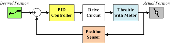
In traditional throttles, the control task was simply done by a mechanical link between the acceleration pedal and the throttle. For the electronic throttles, the position of the acceleration pedal is converted into an electric signal and sent to the electronic control unit (ECU). The control objective is to make the throttle move to the intended position rapidly and precisely. In this project, the control strategy is closed-loop and uses throttle position feedback through potentiometers built in to the throttle body. The control structure is illustrated in Fig. 1.
Fig. 1. Simple PID control of the electronic throttle.
As shown in Fig. 1, the actual throttle position is compared to the desired value and the difference between them is sent to a proportional-integral-derivative (PID) controller to generate the input signal for the drive circuit. The drive circuit supplies power to the motor moving the throttle valve to the desired position. For a given throttle model, the associated PID parameters can be calculated using classic control theory techniques such as root locus and bode diagrams. In this project, parameters were determined experimentally due to the lack of model parameters for this particular throttle.
System Configuration
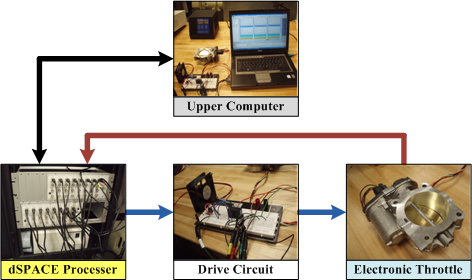
The experimental set-up is illustrated in Fig. 2. The system is composed of four basic parts: an electronic throttle body made by GM, a dSPACE processor with A/D and D/A interfaces, a simple drive circuit, and a laptop system controller (upper computer).
Fig. 2. The configuration of the experimental system.
Electronic Throttle Body
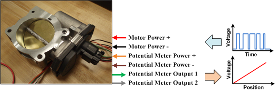
The electronic throttle consists of a regular throttle body, a DC motor with gear transmission, and two potentiometers for sensing the throttle valve position. This module has a 6-pin interface, the definition of which is shown in Fig. 3. The DC motor is driven by a pulse-width-modulated (PWM) signal. The output voltage of the potentiometer is proportional to the throttle position. Two potentiometers are used to improve the accuracy and reliability of the system.
Fig. 3. Pin definition of the electronic throttle.
The dSPACE Processor and Upper Computer
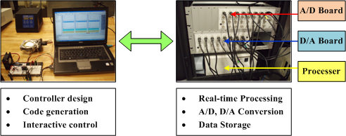
The control algorithm for the electronic throttle was developed in MATLAB/Simulink on the upper computer. Then it was converted into a C code and downloaded to a dSPACE processor. The processor has its own Analog/Digital (A/D) and Digital/Analog (D/A) boards to communicate with the sensor and actuator. The processor is constantly connected to the upper computer for code download, status monitoring and interactive control. The architecture is illustrated in Fig. 4.
Fig. 4. The hardware architecture of the controller.
Drive Circuit
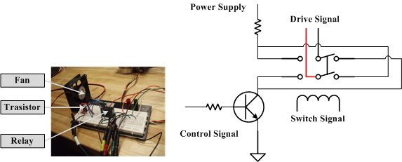
To operate the motor, a drive circuit is required. In this experiment, we used a transistor and a relay to form a simple drive circuit, which is shown in Fig. 5. The transistor operates in an on/off manner to generate the PWM drive signal (1 kHz). The duty cycle is controlled by the dSPACE processor to regulate the motor current (speed). A double-pole double-throw (DPDT) relay is used to change the rotation direction of the motor. The rated voltage and current of the DC power supply were set to 12 V and 1.6 A, respectively.
Fig. 5. The drive circuit.
Results
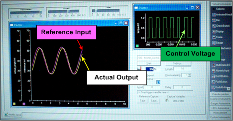
In this experiment, a sinusoidal signal (frequency: 0.4Hz, amplitude: 13 degrees, amplitude-shift: 40 degrees) is applied to the controller as the reference input. Then the actual throttle position is recorded and compared to the reference signal to determine the required response of the electronic throttle. The comparison between the reference input and actual output is shown in Fig. 6. The actual mechanical response of the throttle was also recorded using a digital camera and is shown in a video clip. These results show that the throttle does a good job of tracking the reference trajectory.
Fig-6 Results of the reference input, actual output and control voltage