Modeling a Center-driven Dipole with Microstripes
Geometry and setup |
Geometry: L= 1 m, a = 0.5 mm
Model parameters:
- Frequency: 50 MHz ~ 400 MHz
- Duration: 36020 (Time*c)
- Residual energy: Unused
Mesh definition:
- Extents: 40%
- Cell size wanted: Maximum = default/4.0, Minimum = Maximum/40
- Automesh
Excitation: Voltage source (1 V, 50 ohms)
 floemc_dipole.zip
|
Simulation result |
Simulation time: 11 hrs 17 mins
Time step: 5.2166285E-13
Maximum model frequency: 2.4867681E+09
Number of time steps: 234979
MNumber of samples: 1224
Number of cells: 1259751
Memory Allocated: 123757665
|
Decisions the user must make that affect the accuracy
of the result |
- Extent: 40% in all directions, larger extent is not needed in this model.
- Duration time: default value which is decided based on the extent settings.
- Cell size wanted: Among all the options, select: Maximum = default/4.0, Minimum = Maximum/40;
Coarser cell sizes yielded less accurate results.
The default value resulted in errors that kept the code from running.
|
Comments |
- Adding the source requires a gap between the two wires. What is the source gap length?
In this model, the interval between two antenna parts is 1 mm.
- What is effect of a small change in wire radius?
Changing the radius from 0.5 mm to 2.5 mm, shifts the resonant frequency from 144.2 to 143.6 MHz.
The impedance at 150 MHz changes from 79.2+j46.1 ohms to 84.2+j39.0 ohms.
More information...
- Where should the absorbing boundary be located?
A larger-than-default grid was required to get good results. To avoid running the simulation
for a long time, the computational domain and duration time need to be selected properly.
In this model, the size of the absorbing boundary was set to a 40% extent in all directions.
More information...
- Can we use the "wire model" feature to represent the dipole?
Yes, the dipole antenna can be modeled using the "wire model" feature drastically reducing
the simulation time.
More information...
- What if we model the dipole as a flat ribbon?
We can substitute a 2-mm flat ribbon for a 0.5-mm radius round wire. This greatly decreases
the simulation time without reducing the accuracy of the result.
More information...
|
|
|
Screen shots
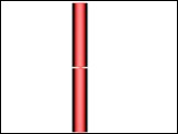
Fig. 1. Simulation model
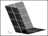
Fig. 2. Simulation meshes
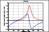
Fig. 3. Input impedance
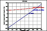
Fig. 4. Input impedance at the first resonant frequency
|
|
)
)
)
)