Modeling a Powerbus with Microstripes
Geometry and setup |
Double-sided PCB:
- Size: 125 mm × 100 mm × 1 mm
- Top and bottom metal: PEC
- Dielectric: FR4, εr = 4.5, conductivity = 0.005 (dielectric loss tangent = 0.015 @ 1.33 GHz)
Model parameters:
- Frequency: 5 MHz - 2 GHz
- Duration: 20000 (Time*c)
- Residual energy: -60 dB
Mesh definition:
- Extent: 30%
- Cell size wanted: Maximum = Default, Minimum = Maximum/40
- Automesh
Excitation: Voltage source (1 V, 50 ohms)
 floemc_powerbus.zip
|
Simulation result |
Simulation time: 30 mins
Time step: 2.4162933E-13
Maximum model frequency: 2.0400005E+09
Number of time steps: 288584
MNumber of samples: 572
Number of cells: 13079
Memory Allocated: 7223090
|
Decisions the user must make that affect the accuracy of the result |
- Extent: 30% in all directions, there is no need to set a larger extent.
- Duration: The default value is 4000 mm. This value is too small for the response to die out.
20000 mm or more is needed.
- Cell size wanted: Set Maximum cell size to the default value. Change the Minimum cell size to
"Maximum/4.0". Finer cell sizes are fine, but will require greater simulation time.
- The default feed wire radius is not appropriate for this model. It should be set to a larger, more realistic value
(0.5 mm in this model).
|
Comments |
- Can MicroStripes model this highly resonant structure?
For such a highly resonant structure, there is a lot of energy trapped between
the parallel plates. Time domain codes need to run a long time before the response
has settled sufficiently. Adding more loss to the dielectric or the planes would
decrease the simulation time (but would also, of course, affect the result).
- Is the radius of the feed wire (which is used to define a wire port) important in this model?
A 1-volt, 50-ohm wire port was the source used in this model. The wire radius had to be changed
to a larger-than-default value. The default value yielded an inaccurate input impedance.
More information...
- Can a feed wire be located at the edge of the plane surface?
Although it works in this model, locating a feed wire on a surface edge can produce unpredictable
results. The "Power bus with cable" model on this web site is an example of this.
- Can MicroStripes model a dielectric material with constant loss tangent?
No. Lossy dielectrics in Microstripes have a constant conductivity.
Microstripes cannot model materials with constant loss tangent. In this example,
we modeled the dielectric using the conductivity required to give accurate results in the middle
of our frequency range. This resulted in too much loss at lower frequencies and not enough loss
at higher frequencies.
More information...
|
|
|
Screen shots
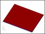
Fig. 1. Simulation model
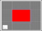
Fig. 2. Simulation meshes
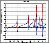
Fig. 3. Input impedance
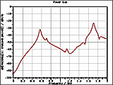
Fig. 4. Electric field at 3 m, θ=0°, φ=0°
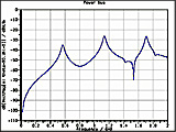
Fig. 5. Electric field at 10 m, θ=90°, φ=0°
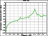
Fig. 6. Electric field at 10 m, θ=90°, φ=90°
|
|
)
)
)
)
)
)