Modeling Powerbus and Cable with Microstripes
Geometry and setup |
Double-sided PCB:
- Size: 125 mm × 100 mm × 1 mm
- Top and bottom metal: PEC
- Dielectric: FR4, εr = 4.5, conductivity = 0.005 (dielectric loss tangent = 0.015 @ 1.33 GHz)
Model parameters:
- Frequency: 5 MHz - 2 GHz
- Duration: 100000 (Time*c)
- Residual energy: -60 dB
Mesh definition:
- Extents: 40%
- Cell size wanted: Maximum = default, Minimum = Maximum/20
- Automesh
Excitation: Voltage source (1 V, 50 ohms)
 floemc_powerbus_cable.zip
|
Simulation result |
Simulation time: 6 hrs
Time step: 9.0658985E-13
Maximum model frequency: 2.0000000E+09
Number of time steps: 371125
MNumber of samples: 2749
Number of cells: 434750
Memory Allocated: 49612724
|
Decisions the user must make that affect the accuracy of the result |
- Extent: 40% in all directions, there is no need to set a larger extent.
- Duration: default value is 28000 mm, this value is too small for the signal to die out,
in this model, 100000 mm or more is required.
- Cell size: Set Maximum cell size to the default value. Change the Minimum cell size
to Maximum/2.0. Finer cell sizes are ok, but require more simulation time.
- Feed wire radius should be set to a realistic value (0.5 mm in this model).
- The feed wire must be located a small distance away from the surface edge.
|
Comments |
- Can a wire port be located on the edge of the surface?
In this model, the feed wire cannot be located on the surface edge.
It must be located 2.5 mm away from the edge. The cable must be located 5 mm away from the edge.
- Can we model the 2-mm cable using the "wire model" feature?
The radius of the wire cable is 1 mm in this model. We tried to change the value
to 2 mm, but mesh errors prevented the program from running.
- How can we model the ground plane?
The ground plane can be modeled as an electric wall (i.e. set the boundary condition to electric wall).
- What if we model the cable as a flat ribbon?
An 8-mm wide ribbon can be used to model the wire. The results show that such a substitution
has sufficient accuracy and significantly decreases the simulation time.
More information...
- Can MicroStripes model dielectric materials with constant loss tangent?
No. Lossy dielectrics in Microstripes have a constant conductivity.
Microstripes cannot model materials with constant loss tangent. In this example,
we modeled the dielectric using the conductivity required to give accurate results in the middle
of our frequency range. This resulted in too much loss at lower frequencies and not enough loss
at higher frequencies.
More information...
|
|
|
Screen shots
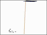
Fig. 1. Simulation model
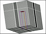
Fig. 2. Simulation meshes
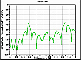
Fig. 3. Electric field at 10 m, θ=0°, φ=0°
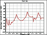
Fig. 4. Electric field at 10 m, θ=90°, φ=0°
Fig. 5. Electric field at 10 m, θ=90°, φ=90°
|
|
)
)
)
)
)