
Zuo Zhou , David A. Ladner
Published in the Journal of Separation and Purification Technology
Citation: Computational modeling of discrete-object feed spacers attached directly onto reverse osmosis membranes for enhanced module packing capacity and improved hydrodynamics
Zhou Z., Ladner D.A. (2022) Separation and Purification Technology, 300 , art. no. 121727
Abstract
In the recent decade, various printing technologies have been under development for producing spacers in reverse osmosis (RO) and nanofiltration (NF) modules. One manufacturing technology directly attaches discrete objects or features to the feed-side membrane surface. The novelty of this method is that tangential flow over the membrane is much less obstructed than with conventional feed spacers, and thus thinner spacers can be built. Within the same cylindrical module volume, more layers can be packed and more membrane surface area can be added to achieve higher permeate flow rates. The research goal of this paper is to design efficient models that help us discover the best parameters for discrete-object spacers. Spacer heights and spacer patterns are directly related to longitudinal pressure drop and concentration polarization (CP). Computational fluid dynamics (CFD) is useful in helping expedite the process of discovering the best designs with both low pressure drop and low CP. Simulations investigated spacer shapes including regular cylinders, elliptical cylinders, and airfoils. Ellipses with a length:width ratio of 2.4 while maintaining a between-feature distance of 6 mm were optimal for minimizing pressure drop. Spacer heights ranging from 200 µm to 500 µm were simulated to discover the height to achieve the same pressure drop as a 30 mil (0.762 mm) conventional spacer. Simulation results indicate that discrete-object spacers with elliptical design can greatly increase water productivity in a spiral-wound module by increasing packing capacity. These designs also reduce CP by 7% by improving the hydrodynamics, compared to empty channels.
1. Introduction
Reverse osmosis (RO) membranes are extensively used as a desalination technology [1], and are experiencing rapid growth in both municipal and industrial water treatment [2], [3]. One problem in all RO systems is their high capital and operating costs. To reduce capital cost, it is important to improve the performance of the membranes. A method to achieve greater performance is to enhance permeate flux through spacers that alter the flow and mass transfer patterns [4], [5], [6], [7], [8]. A particularly advantageous spacer design is one that enhances the hydrodynamics with very thin features. Thin features create a thin flow channel between membrane leaves, which improves the packing capacity of the module. By promoting mass transfer, improving water productivity, and increasing the packing capacity, more clean water can be produced in a smaller plant footprint and the capital cost of the system can be reduced.
Feed spacers are used in spiral wound membrane modules to create intermembrane space and increase water mixing [9]. It has been suggested that a thin feed channel spacer with low pressure loss at a high mass transfer rate can be advantageous for improved water productivity [10]. Due to its important role in the process, many groups have investigated spacer design both numerically and experimentally [11], [12], [13], [14]. Different geometries such as ladder shapes [15], [16], [17], [18], diamonds [18], spacers with modified filaments or twisted tapes [19], and multi-layer spacers [19] were investigated and their mass flow results were studied. However, due to their complex geometries it is not feasible to manufacture these spacers using conventional manufacturing techniques. In recent years 3D printing technology (also called additive manufacturing) has gained attention for its potential ability to build spacers with complex geometries [20].
Available literature focuses on various aspects of 3D-printed spacers. These spacers were printed as one connected sheet using 3D printing technology. Yanar et al. analyzed membrane spacer materials and showed that printing with different materials results in variations in spacer geometry that can affect fouling [21]. Lee et al. [22] looked into 3D printing technologies for creating various components of spiral-wound modules and observed that the typical resolutions of the current additive manufacturing machines are on the order of micrometers which make them useful for printing spacers. With the help of 3D printing technology, new spacer geometries have emerged, such as sinusoidal [23], [24], wave-like [25], pillar-like [26], column shaped [27], honeycomb-shaped [28], and triply periodic minimum surface [20]. These spacers lend support to the promise of 3D printing technology for improving membrane performance through reducing fouling or improving energy efficiency.
The unique aspect of the feed spacers discussed here is that they are discrete objects that are attached directly onto the membrane surface using 3D printing, which is different from the manufacturing techniques that are usually discussed with spacer technology [29]. Usually, spacers are built as one complete sheet of material that is placed between membrane leaves when rolling a spiral wound module; the spacer is not glued or adhered to the membrane. Here we discuss spacers that are printed layer by layer to create an array of objects or features on the membrane. Each object is separate from all the others; there are no connecting filaments from one feature to another. This allows a great deal of open, unobstructed flow volume. A variety of techniques is under development for creating these types of spacers, such as ink-jet printing, off-set printing, and stereolithographic methods [30]. None of these techniques has yet been commercialized, though development is underway. Spacer materials can include food grade polymers, food grade epoxies, thermoplastics, and waxes [31]. Because the tangential flow around discrete-object spacers is much less obstructed than with conventional spacers, the feed channel thickness can be much lower. Tests have been performed with feed channels as thin as 5 mil (0.13 mm), which is much thinner than conventional spacers that are usually between 26 and 34 mil (0.66 mm and 0.86 mm) [9]. These spacers can greatly increase the amount of membrane area packed in a module, and therefore increase the flow rate of clean water that can be produced.
One concern with thinner spacers is that longitudinal pressure drop can increase, which increases energy consumption. This would be especially true if the conventional mesh spacers were made thinner because they have filaments that block the longitudinal flow path. The discrete-object spacers investigated here take up much less cross-sectional area than conventional spacers because each feature need not be connected to one another. It is reasonable to believe that designs exist where the spacers will not cause extra pressure drop even when the channel width is thinner than conventional ones.
Concentration polarization (CP) is another key aspect for designing spacers applied in membrane systems due to its negative influence on transmembrane flux [32]. CP is a phenomenon that exists in all membrane purifications, during which a salt concentration gradient is established on the membrane surface under the effect of transmembrane driving forces. CP can be reduced by making the flow channel more tortuous or by increasing the crossflow velocity, but both of those come with a cost of increased longitudinal pressure drop. The goal is to develop a spacer that can reduce CP while maintaining low longitudinal pressure drop. Being able to predict CP is important in designing membrane modules for reduced surface fouling and scaling properties [33]. The increased mixing caused by spacers can reduce both CP and fouling because the turbulence minimizes dead zones where CP and foulants often accumulate [34]. Many models of membrane processes reduce the mathematical description of spacers to bulk parameters like porosity and tortuosity [35]. For designing new spacers with detailed geometries, higher resolution spatial models are required. Some simulations have been performed to study the CP of spacers at a more detailed resolution [5], [13], [36], [37], but they usually use 2D domains which are not adequate for evaluating 3D-printed spacers where flow around each element affects CP.
Computational fluid dynamics (CFD), as a widely used analysis tool in membrane separations [38], was adopted here to simulate the fluid flow through numerical methods [39]. Many research groups have studied feed spacers with CFD methods. Ali et al. studied column shaped spacers with improved energy efficiency by simulating velocity and shear stress profiles [27]. Chong et al. simulated the hydrodynamics and mass transfer of submerged-type spacers to discover more promising designs under high feed rate [40]. Toh et al. and Kerdi et al. both ran CFD models on perforated spacers to reduce pressure loss and increase fouling resilience in spiral wound membrane modules [41], [42]. All of these published papers looked at the relationships between pressure drop and mass transfer to optimize their spacer design. As we mentioned in our previous paper, it is important to fully couple flow and solute transport equations [43], [44]. In one modeling approach, investigators simplified governing equations and assumed that the permeation velocity does not depend on axial position and therefore remains constant along the length of the membrane channel [45]. This decoupling of flux and solute concentration can decrease the accuracy of the models since permeate flux is affected by osmotic pressure that increases down the channel. Another group used analytical models to theoretically predict permeation flux, and used numerical simulation to predict flow and mass transfer [46]. That approach is better than assuming constant flux, but is still not a complete coupling. Xie et al. [4] studied CP in spacer filled channels by fully coupling flow and mass transport equations. They predicted CP mitigation that was consistent with experimental results. In our models, flow and mass transport equations are likewise combined to solve for mass transfer. Osmotic pressure is linearly related to salt concentration, and flux is calculated by taking into account both the hydraulic and osmotic pressures.
The work described in this manuscript is organized into three phases. Phase 1 was channel thickness optimization. We determined the minimum realistic thickness of a flow channel with discrete-object spacers that had the same pressure drop as a channel with conventional mesh spacers. Phase 2 was feature shape optimization. We performed a suite of simulations to investigate elliptical and airfoil designs to select those with potential for the least pressure drop. Phase 3 was feature array optimization. We used the optimal flow channel thickness from Phase 1 and combined it with the optimal geometry from Phase 2 to conduct a series of simulations with arrays of discrete features to investigate CP effects. This is the first paper of which we are aware that describes discrete-object feed spacers and the optimization of their geometry. Through three phases of simulation we found spacer designs that result in minimal pressure drop and reduced CP.
2. Materials and methods
A variety of simulations was performed in both 2D and 3D using COMSOL Multiphysics 5.5 run on the Palmetto Cluster, Clemson University’s primary high-performance computing resource. Models were tailored to use COMSOL’s finite-element approach to solve for fluid flow (e.g. pressure and velocity), transport of diluted species (e.g. concentration, advection, and diffusion), and membrane performance (e.g. flux and pressure drop). Inspiration for initial designs was taken from industry efforts to manufacture discrete-object spacers [30], [47], [48]. All simulations were performed as steady state studies.
2.1. Geometries studied
2.1.1. Phase 1: 3D geometries for channel thickness optimization
A membrane channel with conventional spacers was first built to investigate its pressure drop. Then several channels filled with discrete-object spacers were evaluated with heights varying from 100 µm to 500 µm.
Conventional diamond-mesh spacer simulations had channel heights of 0.76 mm (30 mil), which is a common thickness found in modules on the market. The thickness of each filament of the conventional spacer was half of the channel height and filaments were placed on top of each other in a criss-cross pattern (Fig. 1a). Conventional spacer simulations required larger computing capacity than the 3D printed designs due to their more complex geometry. Therefore, the models had to be kept to a reasonable size. Models with different domain lengths including 6 mm, 12 mm, 18 mm, and 24 mm were simulated and pressure drop values were compared (data shown in supplemental material Fig. S1). To avoid the entrance effects, all models had an entrance length of 1 m so that it had a fully developed laminar flow profile. At 12 mm and longer, the pressure drop per length (Pa/m) values were similar (within 5% of one another), so we chose 12 mm as the domain length (Fig. 1a and 1b). The domain width was 6 mm. Due to the complex geometry of conventional spacers, building periodic boundary conditions would be difficult because the edges are not necessarily repeating. To keep these two models consistent, none of them applied periodic boundary conditions.

Fig. 1. Membrane channels with conventional spacers (a and b) and discrete-object spacers (c and d). The height of the conventional-spacer filled channel was 0.76 mm, while the height of the discrete-object spacer filled channel varied in the first series of studies by performing a parametric sweep.
For discrete-object spacers, four rows and two columns of cylindrical features were simulated. (More shapes will be reported later in the paper.) Here, the spacer parameters were based on a design that has been prototyped in which the ratio of spacer length and distance between the centers of two nearby spacers was equal to 1:6 [31]. In these models, we studied the spacers when d was 1 mm and compared the results with the conventional spacers.
A conceptual model was built to help explain the boundary conditions (Fig. 2). The feed enters the domain on the left side, and the permeate leaves the domain on the right side. The top surface is the membrane, indicated in grey. The rate of permeation (um) was calculated using Eq. (1). Temperature (293 K) was held constant here and in all the simulations of this paper, thus fluid viscosity (1.00 mPa·s) was also constant. The membrane permeability (A), was held at 

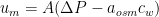

Fig. 2. Conceptual model for 3D geometries used in Phase 1 to study pressure drop in thin channels.
2.1.2. Phase 2: 2D geometries for feature shape optimization
Twenty 2D models were run to investigate the shape of a single feature that would produce the least pressure drop in the flow channel (Fig. 3). The geometries included cylinders, elliptical cylinders, and airfoils. These shapes have smooth characteristics that could potentially reduce drag and improve hydrodynamics. Spacers were set to have the same width, the same length, or the same attached area to the membrane surface to investigate how feature characteristics affected pressure drop. The simulation space for each model was 18 mm in length and 6 mm in width. The simulations incorporated laminar flow with an inlet velocity of 0.1 m/s and an outlet pressure of 400 psi. Periodic boundary conditions were used on the two sides parallel to the flow to minimize edge effects.

Fig. 3. Spacer feature geometries for Phase 2. (a) Ellipses with the same width (1 mm) but different lengths (0.5 mm to 4 mm). (b) Ellipses with the same length (4 mm) but different widths (0.5 mm to 4 mm). (c)(d) Ellipses and airfoils with the same total area, but different x-axis and y-axis lengths. The x-axis length ranged from 1 mm to 3 mm for 2D simulations, and y-axis length ranged accordingly.
2.1.3. Phase 3: 3D geometries for feature array optimization
3D geometries were built to investigate CP. It is not feasible or necessary to build models that represent the full size of a spiral-wound RO element with enough resolution to capture mm-scale flow patterns around spacer features. We chose a size that matched the commonly used SEPA cell apparatus [4], [23], [49] (Fig. 4), which is designed for experiments that mimic spiral-wound elements using a small membrane coupon. The size of the flow channel in the SEPA cell is 146 mm in length, 95 mm in width, and 0.42 mm in height.

Fig. 4. Flow channel dimensions for the SEPA test cell, which is the domain geometry chosen for Phase 3.
To determine the ideal parameters of the discrete-object spacers including the feature size and the between-feature distance, a series of calculations was performed based on the diagram in Fig. 5. Our goal was to find the maximum distance between spacers while making sure the membrane channels would be well separated. We assumed a spiral wound element with a permeate collection tube having a radius r. We also assumed that to create a spacer feature that will not topple over, its height (h) should be no taller than its width (d), thus each spacer feature has a square cross-sectional area as shown by the purple squares in Fig. 5.

Fig. 5. Diagram used for calculation of between-feature distance (D, indicated by the pink arc in the figure) based on a permeate collection tube of a spiral wound element with an inner dimension of 19 mm (r = 9.5 mm).
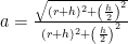
The distance from the center of the permeate tube to the corner of a spacer feature (denoted a in Fig. 5) was calculated with.
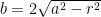
The distance b in Fig. 5 was then calculated with.
With h and b defined, the angle (θ + γ) was derived using.

After knowing the angle θ + γ we calculated the between-feature distance (D) using the arc length indicated in red in Fig. 5:

One common permeate collection tube in RO modules has a 9.5 mm radius. The results of the pressure drop analysis for thin channels (Section 3.1) showed that 0.42 mm was a promising channel height. Using these numbers, a spacer with features having height (h) and width (d) equal to 0.42 mm built around a permeate collection tube with radius r = 9.5 mm, the between-feature distance was 6 mm.
To study patterns that were offset from one row to another we defined the “staggering level.” The staggering level is a percentage number from 0% when the patterns were perfectly in line to 100% when the patterns were completely staggered (Fig. 6).

Fig. 6. Spacer offsets including in-line and staggered. The 100% staggered offset is when the second row of spacers fall in the middle of the first row.
2.2. Mesh generation
For the 3D models in Phases 1 and 3, tetrahedral meshes were generated and the number of elements was typically about 500,000 for each model. For the 2D models of Phase 2, triangular meshes were built and the number of elements was about 3000 for each model. Mesh sensitivity analysis was conducted to make sure that the simulation results did not vary significantly if the mesh density were increased. Details of the mesh sensitivity analyses can be found in the supplemental material Figs. S4 and S5.
2.3. Governing equations
The simulations of Phases 1 and 2 (channel thickness optimization and feature shape optimization) evaluated only the fluid flow, which was accomplished by numerically solving the Navier-Stokes Eq. (6) and the continuity Eq. (7) where ρ is density, u is fluid velocity, P is pressure, and µ is dynamic viscosity.
ρ(∇ • u)u = − ∇P + μ∇ • (∇u + ∇uT) —- eq (6)
∇ • u = 0 —- eq (7)
To accomplish the Phase 3 simulations (feature array optimization, which included an evaluation of CP) Eqs. (6), (7) were used for fluid flow and the transport of salt was added using the convective-diffusion Eq. (8) where c is the concentration and D is the diffusion coefficient.
U∇ • c = D∇2 c —- eq (8)
Momentum and mass transport were fully coupled in Phase 3 simulations in the sense that the Navier-Stokes, continuity, and convective–diffusion equations were solved simultaneously and flux was set as a boundary condition to calculate the concentration profile.
3. Results and discussion
3.1. Pressure drop for Phase 1: Channel thickness optimization
Pressure drop was first studied in membrane simulations with conventional spacers compared to discrete-object spacers. The study domain and spacer configurations are shown in Fig. 1. One conventional spacer type was used with a height set at 30 mil (0.76 mm). One discrete-object spacer pattern was used (1 mm diameter circular pillars with 6 mm between-feature distance), but a parametric study was performed to vary the height from 0.2 to 0.5 mm. Pressure drop results are shown in Fig. 7 when maintaining the same (a) inlet velocity or (b) volumetric crossflow rate; as the spacer heights increase, pressure drop decreases. The pressure drop found in the simulation of the conventional spacer was 13,000 Pa/m, which compared well with typical pressure drops for spiral wound elements used in practice [50].

Fig. 7. Pressure drop for discrete-object spacers forming various channel heights under (a) constant crossflow velocity (10 cm/s) and (b) constant volumetric crossflow rate (0.912 cm3/s). The pressure drop results for conventional spacers at 0.76 mm (30 mil) are shown with a blue diamond. A dotted horizontal line is drawn through the data point to guide the eye to find the height (x value) of circular spacers having the same pressure drop.
An important attribute of any spacer is the area where water flow is blocked by the spacer making contact with the membrane; we define this as the “blocking area” and report it as a percentage of blocked area compared to the total area. In our simulations, the conventional spacer blocking area was 3.2% and the discrete-object spacer was 2.2%. Literature review was conducted to estimate the blocking area in common spacer filled channels used in practice. Calculation shows that the blocking area can range between 3.9% and 8% (see supplemental material Fig. S2) [51]. Reduced blocking area can be beneficial for improving permeate flow rate by increasing the active membrane area.
Results show that given the same crossflow velocity, discrete-object spacers caused the same pressure drop as the conventional spacer at a height of 0.32 mm (Fig. 7a). This was less than half as thick as the conventional spacer (0.76 mm); therefore, within the same volume, when using discrete-object spacers instead of conventional spacers, more membrane layers can be packed. A caveat to packing in more membrane layers is that more of the module would be taken up by membranes and permeate carriers, so the crossflow velocity would have to increase to accommodate equal feed flow rate into the module. To evaluate these effects, a comparison with the same volumetric crossflow rate was performed; in each simulation the crossflow velocity changed according to the channel height. The results from this analysis show that the thickness of the discrete-object spacers yielding equal pressure drop as the conventional spacer was 0.42 mm (Fig. 7b), still much lower than the conventional-spacer thickness.
Typical spiral wound membrane modules (Fig. 5) are assembled with each membrane “sandwich” containing a layer of feed spacer, a layer of membrane, a layer of permeate carrier, and another layer of membrane. We measured 28 layers in a typical 4-inch module (Hydranautics SWC5) to be 32 mm, yielding a thickness of 1.14 mm per sandwich. The feed spacer was 0.76 mm. If the feed spacer were replaced with a discrete-object spacer having a thickness of 0.42 mm the sandwich would be only 0.8 mm; thus, 32 mm/0.8 mm = 40 sandwiches can be packed into the same module. This yields an increase in membrane area of (40 − 28)/28 = 43%.
3.2. Pressure drop for Phase 2: Feature shape optimization
After deciding the channel height for discrete-object spacers, single elements in 2D simulations were studied to optimize the geometry to minimize pressure drop around individual features. Elliptical (including one circular shape), and airfoil geometries were studied. These shapes were of interest because airfoils are often used for low-drag situations such as airplane wings, while ellipses were expected to have similar pressure drop reduction benefits as airfoils but would be easier to manufacture because they do not have the sharp trailing edge of airfoils. The area was maintained constant at π/4 mm2 (corresponding to a circular shape with 1 mm diameter) while the lengths and widths were varied. Results show that ellipses and airfoils performed similarly (Fig. 8). The sharp trailing edge of the airfoils did not result in lower pressure drop, so we focused on ellipses for the remaining simulations reported here.

Fig. 8. Results for ellipses and airfoils with different lengths and widths while maintaining the same area (π/4 mm2). (a) Pressure drop results for both ellipses and airfoils. (b) Velocity profile and streamlines for ellipses. (c) Velocity profile and streamlines for airfoils. (d) Shear stress profile for ellipses. (e) Shear stress profile for airfoils.
Fig. 9 shows the effects of varying ellipse width while maintaining constant length (panel a) and the effects of varying length while maintaining constant width (panel b). When lengths were kept at 4 mm, it is straightforward to notice that the pressure drop increased as the width increased (Fig. 9a). In Fig. 9b, when widths were kept at 1 mm, pressure drop first decreased drastically as the length increased. This is because shear stress decreased as the x-axis length increased. When the length reached between 2 mm and 3 mm (meaning the length to width ratio was between 2:1 to 3:1), the pressure drop value was lowest. As the length increased beyond 3 mm, pressure drop increased again because the additional surface in contact with fluid (having a no-slip boundary condition) increased the overall drag.

Fig. 9. Results for ellipses with varying widths or lengths. (a) Pressure drop for ellipses with 4 mm length and varying width (from 0.5 mm to 4 mm). (b) Pressure drop for ellipses with 1 mm width and vaying length (from 0.5 mm to 4 mm). (c) Shear stress for the ellipses of panel a. (d) Shear stress for the ellipses of panel b.
Further models were evaluated to test additional length to width ratios between 2:1 and 3:1 (Fig. 9b inset). When the ratio was 2.4:1, pressure drop was lowest. According to Fig. 8, when varying both widths and lengths at the same time and keeping the total area the same, the best ratio was 2.6:1 for ellipses and 2.8:1 for airfoils. The overall conclusion is that when the spacer width is determined, increasing spacer length will increase pressure drop; however, when the spacer length is determined while the width is changing, the best result for pressure drop is when the length and width ratio is between 2:1 and 3:1. The studies on these single features give us a direction for designing geometries with low pressure drop that can be arrayed on the membrane surface to create a spacer that saves energy and therefore reduces the cost of an entire membrane unit.
3.3. Concentration polarization for Phase 3: Feature array optimization
For Phase 3 simulations the models were first validated through comparing 2D and 3D results. The concentration profiles were similar (Fig. 10), giving us confidence that the models were behaving well. The shape of the concentration profile fits the results found with a classical Sherwood correlation as we described in our previous work [43].

Concentration profiles were characterized for both an empty channel and channels filled with discrete-object spacers and the quantitative results are shown through the calculation of CP factor, which is defined as the ratio of surface concentration (cm) to bulk concentration (cb). Discrete-object spacers with elliptical cylinders (length:width = 2.4:1) have in-line and staggered offsets.
The comparison for CP, shear stress, and permeate flux profile is shown in Fig. 11. Concentration and shear stress profiles help to visualize how the hydrodynamics of the channels change due to the addition of the spacers. The salt concentration in an empty channel (Fig. 11a1) followed a classical CP pattern of increasing along the length of the channel. When spacer features were introduced (Fig. 11a2) the salt concentration still followed a classical CP pattern in general, but the magnitude of CP was reduced. This is an important finding for the discrete-object spacer concept: the spacer features break up the flow and increase mixing, which decreases the level of CP in the membrane channel. Shear stress is an important factor in mixing; while the bulk shear stress in the channel did not change dramatically when spacers were added (as indicated by the relatively similar colors in Fig. 11b1, b2, & b3), the local shear stress around the features was elevated.

Fig. 11. Concentration profile for (a1) an empty channel, (a2) a channel filled with in-line spacers, and (a3) a channel filled with staggered spacers. Shear stress profile for (b1) an empty channel, (b2) a channel filled with in-line spacers and (b3) a channel filled with staggered spacers. Permeate flux profile for (c1) an empty channel, (c2) a channel filled with in-line spacers, and (c3) staggered spacers. All channel heights are 0.42 mm. All spacers are in an elliptical shape with a length of 1 mm and a width of 0.42 mm. The distance between features is 6 mm. In column 2 the in-line spacers are classified as 0% staggered. In column 3 the spacers are 100% staggered.
Discrete-object spacers successfully improved permeate flux, especially towards the end of the channel (indicated by the lighter blue color extending further down the channel in Fig. 11c2 and c3). The average permeate flux results are shown along with the average CP results in Fig. 12, giving us a more quantitative understanding. Compared to the empty channel, CP was reduced by about 7% for all discrete-object spacers regardless of staggering level, suggesting that the presence or absence of features is more important than their arrangement. There was only a slight benefit in terms of permeate flux; flux increased by about 0.64% for all of the discrete-object spacers compared to the empty channel. The average permeate flux values are shown in Fig. 12.

Fig. 12. (a) CP and (b) permeate flux results for models with an empty channel and spacers with different staggering levels. The staggering degree goes from 0% (in line) to 100% (completely staggered).
Since spacers affect both mixing and pressure drop, one way to evaluate their performance is to use the Sherwood number and Power number as others have described [19]. The Sherwood numbers for all of the Phase 3 models with spacers were between 10.43 and 10.56, which was a little higher than the empty channel Sherwood number of 9.16 (Fig. S3). This indicates that the mixing was better with spacers than without, but there was little difference when staggering level was adjusted. The Power numbers for the spacer models were between 22,165 and 22,258, which was higher than the empty channel Power number of 20,616 (Fig. S3). Thus the pressure drop was larger with spacers than without, but again there was little difference among staggering levels. All of the Sherwood and Power numbers were quite lower than those reported for conventional spacers [19], indicated that there is less mixing with these discrete-object spacers, but also a lower pressure drop penalty. The advantage of printing individual objects that are not connected to one another is not that they provide more mixing than conventional spacers, but that they create a more open flow path and the opportunity to pack more membrane area into the module.
4. Conclusions
Discrete-object spacers with improved hydrodynamics and packing capacity were evaluated using computational models. Both 2D and 3D models were built to expedite the discovery of the best arrangement. Results show that 3D spacers that are directly printed onto the membrane surface can enable modules to be built with thinner feed channels than conventional designs while having the same longitudinal pressure drop. For example, if a conventional net-like spacer creates a 0.76 mm channel and has a pressure drop of 13 kPa/m, a discrete-object spacer can form a 0.42 mm channel having the same pressure drop. Such thinner feed channels would mean the membrane packing capacity in a module is increased by 43%. The shape of discrete-object features can also be optimized to yield minimal pressure drops. Airfoils and ellipses with different lengths and widths were investigated; these performed similarly to one another, but it is expected that ellipses would be easier to manufacture in practice. The best ellipse shape had a length to width ratio of 2.4. Arrays of 3D discrete-object features were modeled to evaluate their effects on CP. Arrays of 1 mm wide features with between-feature distances of 6 mm resulted in CP reduction of 7% compared to an empty channel. The layout of the spacers (whether inline or staggered) did not play a big role in the CP results.
5. CRediT authorship contribution statement
Zuo Zhou: Methodology, Software, Validation, Formal analysis, Writing – original draft, Writing – review & editing, Visualization.
David A. Ladner: Conceptualization, Resources, Writing – review & editing, Supervision, Project administration, Funding acquisition.
6. Declaration of Competing Interest
The authors declare that they have no known competing financial interests or personal relationships that could have appeared to influence the work reported in this paper.
7. Acknowledgements
The authors gratefully acknowledge funding through the Designing Materials to Revolutionize and Engineer our Future (DMREF) program of the U.S. National Science Foundation, grant number 1534304. We also acknowledge computational support through the Palmetto Cluster, Clemson University’s primary high-performance computing resource.
8. Data availability
Data will be made available on request.
References
[1] T. Ishigami, K. Amano, A. Fujii, Y. Ohmukai, E. Kamio, T. Maruyama, H. Matsuyama, Fouling reduction of reverse osmosis membrane by surface modification via layer-by-layer assembly, Sep. Purif. Technol. 99 (2012) 1–7, https://doi.org/10.1016/j.seppur.2012.08.002.
[2] C. Fritzmann, J. Lowenberg, ¨ T. Wintgens, T. Melin, State-of-the-art of reverse osmosis desalination, Desalination. 216 (2007) 1–76, https://doi.org/10.1016/j.desal.2006.12.009.
[3] D.E. Potts, R.C. Ahlert, S.S. Wang, A critical review of fouling of reverse osmosis membranes, Desalination. 36 (1981) 235–264, https://doi.org/10.1016/S0011-9164(00)88642-7.
[4] P. Xie, L.C. Murdoch, D.A. Ladner, Hydrodynamics of sinusoidal spacers for improved reverse osmosis performance, J. Memb. Sci. 453 (2014) 92–99, https://doi.org/10.1016/j.memsci.2013.10.068.
[5] A.L. Ahmad, K.K. Lau, Impact of different spacer filaments geometries on 2D unsteady hydrodynamics and concentration polarization in spiral wound membrane channel, J. Memb. Sci. 286 (2006) 77–92, https://doi.org/10.1016/j.memsci.2006.09.018.
[6] K.K. Lau, M.Z. Abu Bakar, A.L. Ahmad, T. Murugesan, Feed spacer mesh angle: 3Dmodeling, simulation and optimization based on unsteady hydrodynamic in spiralwound membrane channel, J. Memb. Sci. 343 (2009) 16–33, https://doi.org/10.1016/j.memsci.2009.07.001.
[7] A. Shrivastava, S. Kumar, E.L. Cussler, Predicting the effect of membrane spacerson mass transfer, J. Memb. Sci. 323 (2008) 247–256, https://doi.org/10.1016/J.MEMSCI.2008.05.060.
[8] S. Ma, L. Song, Numerical study on permeate flux enhancement by spacers in acrossflow reverse osmosis channel, J. Memb. Sci. 284 (2006) 102–109, https://doi.org/10.1016/j.memsci.2006.07.022.
[9] A. Siddiqui, N. Farhat, S.S. Bucs, R.V. Linares, C. Picioreanu, J.C. Kruithof, M.C.M. van Loosdrecht, J. Kidwell, J.S. Vrouwenvelder, Development and characterization of 3D-printed feed spacers for spiral wound membrane systems, Water Res. 91 (2016) 55–67, https://doi.org/10.1016/J.WATRES.2015.12.052.
[10] J. Schwinge, P.R. Neal, D.E. Wiley, D.F. Fletcher, A.G. Fane, Spiral wound modules and spacers: Review and analysis, J. Memb. Sci. 242 (2004) 129–153, https://doi.org/10.1016/j.memsci.2003.09.031.
[11] M. Shakaib, S.M.F. Hasani, M. Mahmood, CFD modeling for flow and mass transfer in spacer-obstructed membrane feed channels, J. Memb. Sci. 326 (2009) 270–284, https://doi.org/10.1016/j.memsci.2008.09.052.
[12] C.P. Koutsou, S.G. Yiantsios, A.J. Karabelas, Direct numerical simulation of flow in spacer-filled channels: effect of spacer geometrical characteristics, J. Memb. Sci. 291 (2007) 53–69, https://doi.org/10.1016/j.memsci.2006.12.032.
[13] A.L. Ahmad, K.K. Lau, M.Z. Abu Bakar, Impact of different spacer filament geometries on concentration polarization control in narrow membrane channel, J. Memb. Sci. 262 (1-2) (2005) 138–152.
[14] J. Schwinge, D.E. Wiley, A.G. Fane, Novel spacer design improves observed flux,J. Memb. Sci. 229 (2004) 53–61, https://doi.org/10.1016/j.memsci.2003.09.015.
[15] V. Geraldes, V. Semiao, M.N. De Pinho, Concentration polarisation and flow structure within nanofiltration spiral-wound modules with ladder-type spacers, in, Comput. Struct., Pergamon (2004) 1561–1568, https://doi.org/10.1016/j.compstruc.2004.03.052.
[16] V. Geraldes, V. Semiao, M.N. Pinho, Hydrodynamics and concentration polarization in NF/RO spiral-wound modules with ladder-type spacers, Desalination. 157 (2003) 395–402, https://doi.org/10.1016/S0011-9164(03)00422-3.
[17] V. Geraldes, V. Semiao, ˜ M.N. De Pinho, Flow management in nanofiltration spiral wound modules with ladder-type spacers, J. Memb. Sci. 203 (2002) 87–102, https://doi.org/10.1016/S0376-7388(01)00753-0.
[18] A.I. Radu, M.S.H. van Steen, J.S. Vrouwenvelder, M.C.M. van Loosdrecht, C. Picioreanu, Spacer geometry and particle deposition in spiral wound membrane feed channels, Water Res. 64 (2014) 160–176, https://doi.org/10.1016/j.watres.2014.06.040.
[19] F. Li, W. Meindersma, A.B. de Haan, T. Reith, Novel spacers for mass transfer enhancement in membrane separations, J. Memb. Sci. 253 (2005) 1–12, https://doi.org/10.1016/J.MEMSCI.2004.12.019.
[20] N. Sreedhar, N. Thomas, O. Al-Ketan, R. Rowshan, H. Hernandez, R.K. Abu Al-Rub, H.A. Arafat, 3D printed feed spacers based on triply periodic minimal surfaces for flux enhancement and biofouling mitigation in RO and UF, Desalination. 425(2018) 12–21, https://doi.org/10.1016/j.desal.2017.10.010.
[21] N. Yanar, M. Son, E. Yang, Y. Kim, H. Park, S.E. Nam, H. Choi, Investigation of the performance behavior of a forward osmosis membrane system using various feed spacer materials fabricated by 3D printing technique, Chemosphere. 202 (2018) 708–715, https://doi.org/10.1016/j.chemosphere.2018.03.147.
[22] J.Y. Lee, W.S. Tan, J. An, C.K. Chua, C.Y. Tang, A.G. Fane, T.H. Chong, The potential to enhance membrane module design with 3D printing technology, J. Memb. Sci. 499 (2016) 480–490, https://doi.org/10.1016/j.
memsci.2015.11.008.
[23] P. Xie, L.C. Murdoch, D.A. Ladner, Mitigating membrane fouling with sinusoidal spacers, Desalin. Water Treat. 168 (2019) 56–64, https://doi.org/10.5004/dwt.2019.24406.
[24] J.W. Koo, J.S. Ho, Y.Z. Tan, W.S. Tan, J. An, Y. Zhang, C.K. Chua, T.H. Chong, Fouling mitigation in reverse osmosis processes with 3D printed sinusoidal spacers, Water Res. 207 (2021) 117818, https://doi.org/10.1016/J.WATRES.2021.117818.
[25] Y.Z. Tan, Z. Mao, Y. Zhang, W.S. Tan, T.H. Chong, B. Wu, J.W. Chew, Enhancing fouling mitigation of submerged flat-sheet membranes by vibrating 3D-spacers, Sep. Purif. Technol. 215 (2019) 70–80, https://doi.org/10.1016/j.seppur.2018.12.085.
[26] Z. Han, M. Terashima, B. Liu, H. Yasui, CFD investigation of the effect of the feed spacer on hydrodynamics in spiral wound membrane modules, Math. Comput.Appl. 23 (2018) 80, https://doi.org/10.3390/mca23040080.
[27] S.M. Ali, A. Qamar, S. Kerdi, S. Phuntsho, J.S. Vrouwenvelder, N. Ghaffour, H.K. Shon, Energy efficient 3D printed column type feed spacer for membrane filtration, Water Res. 164 (2019) 114961, https://doi.org/10.1016/j.
watres.2019.114961.
[28] S. Park, Y.D. Jeong, J.H. Lee, J. Kim, K. Jeong, K.H. Cho, 3D printed honeycombshaped feed channel spacer for membrane fouling mitigation in nanofiltration, J. Memb. Sci. 620 (2021) 118665, https://doi.org/10.1016/J.MEMSCI.2020.118665.
[29] J.W. Koo, J.S. Ho, J. An, Y. Zhang, C.K. Chua, T.H. Chong, A review on spacers and membranes: conventional or hybrid additive manufacturing? Water Res. 188 (2021), 116497 https://doi.org/10.1016/J.WATRES.2020.116497.
[30] W.L. Bradford, R.E. Herrington, A.D. Clement, Filtration membrane and method ofmaking same, US Patent 2004/0011723 A1, 2004.
[31] R.E. Herrington, Performance of Super Enhanced PEermeate Flow RO Elements with 3D Spacers Printed Directly on the Membrane Surface, (n.d.) 1–22.
[32] E. Matthiasson, B. Sivik, Concentration polarization and fouling, Desalination. 35 (1980) 59–103, https://doi.org/10.1016/S0011-9164(00)88604-X.
[33] S. Kim, E.M.V. Hoek, Modeling concentration polarization in reverse osmosis processes, Desalination. 186 (2005) 111–128, https://doi.org/10.1016/j.desal.2005.05.017.
[34] R. Rahmawati, M.R. Bilad, N.I.M. Nawi, Y. Wibisono, H. Suhaimi, N. Shamsuddin, N. Arahman, Engineered spacers for fouling mitigation in pressure driven membrane processes: progress and projection, J. Environ. Chem. Eng. 9 (5) (2021)106285.
[35] P.M. Biesheuvel, S. Porada, M. Elimelech, J.E. Dykstra, Tutorial review of reverse osmosis and electrodialysis, J. Memb. Sci. 647 (2022) 120221, https://doi.org/10.1016/J.MEMSCI.2021.120221.
[36] M. Park, J.H. Kim, Numerical analysis of spacer impacts on forward osmosis membrane process using concentration polarization index, J. Memb. Sci. 427(2013) 10–20, https://doi.org/10.1016/J.MEMSCI.2012.09.045.
[37] S. Wardeh, H.P. Morvan, CFD simulations of flow and concentration polarization in spacer-filled channels for application to water desalination, Chem. Eng. Res. Des. 86 (2008) 1107–1116, https://doi.org/10.1016/j.cherd.2008.04.010.
[38] G.A. Fimbres-Weihs, D.E. Wiley, Review of 3D CFD modeling of flow and mass transfer in narrow spacer-filled channels in membrane modules, Chem. Eng. Process. Process Intensif. 49 (2010) 759–781, https://doi.org/10.1016/j.cep.2010.01.007.
[39] M.F. Gruber, U. Aslak, C. H´elix-Nielsen, Open-source Cfd model for optimization of forward osmosis and reverse osmosis membrane modules, Sep. Purif. Technol. 158 (2016) 183–192, https://doi.org/10.1016/j.seppur.2015.12.017.
[40] Y.K. Chong, Y.Y. Liang, W.J. Lau, G.A. Fimbres Weihs, 3D CFD study of hydrodynamics and mass transfer phenomena for spiral wound membrane submerged-type feed spacer with different node geometries and sizes, Int. J. Heat Mass Transf. 191 (2022) 122819.
[41] K.Y. Toh, Y.Y. Liang, W.J. Lau, D.F. Fletcher, CFD study of the effect of perforated spacer on pressure loss and mass transfer in spacer-filled membrane channels, Chem. Eng. Sci. 222 (2020), 115704, https://doi.org/10.1016/J.
CES.2020.115704.
[42] S. Kerdi, A. Qamar, J.S. Vrouwenvelder, N. Ghaffour, Fouling resilient perforated feed spacers for membrane filtration, Water Res. 140 (2018) 211–219, https://doi.org/10.1016/J.WATRES.2018.04.049.
[43] Z. Zhou, B. Ling, I. Battiato, S.M. Husson, D.A. Ladner, Concentration polarization over reverse osmosis membranes with engineered surface features, J. Memb. Sci.617 (2021) 118199.
[44] E. Lyster, Y. Cohen, Numerical study of concentration polarization in a rectangular reverse osmosis membrane channel: permeate flux variation and hydrodynamic end effects, J. Memb. Sci. 303 (2007) 140–153, https://doi.org/10.1016/j.memsci.2007.07.003.
[45] R. Ranjan, S. DasGupta, S. De, Mass transfer coefficient with suction for laminar non-Newtonian flow in application to membrane separations, J. Food Eng. 64 (2004) 53–61, https://doi.org/10.1016/j.jfoodeng.2003.09.012.
[46] T. Ishigami, H. Matsuyama, Numerical modeling of concentration polarization in spacer-filled channel with permeation across reverse osmosis membrane, Ind. Eng. Chem. Res. 54 (5) (2015) 1665–1674.
[47] R. Herringtong, J.E. Dresty, W.M. K., Systems and methods for filtration, International Patent WO 2011/094236 A2, 2011.
[48] K. Roderick, R. Herrington, Flow directing deviced for spiral-wound elements, US Patent 10,471,391 B2, 2019.
[49] D.A. Ladner, A. Subramani, M. Kumar, S.S. Adham, M.M. Clark, Bench-scale evaluation of seawater desalination by reverse osmosis, Desalination. 250 (2010) 490–499, https://doi.org/10.1016/J.DESAL.2009.06.072.
[50] G. Schock, A. Miquel, Mass transfer and pressure loss in spiral wound modules, Desalination. 64 (1987) 339–352, https://doi.org/10.1016/0011-9164(87)90107-X.
[51] J.S. Vrouwenvelder, C. Picioreanu, J.C. Kruithof, M.C.M. van Loosdrecht, Biofouling in spiral wound membrane systems: Three-dimensional CFD model based evaluation of experimental data, J. Memb. Sci. 346 (2010) 71–85, https://doi.org/10.1016/j.memsci.2009.09.025.