On-Board Diagnostic Systems
- Basic Description
-
 On-board diagnostics in automobiles refers to a vehicle's built-in capability to monitor its own vital functions and record/report that information to the vehicle operator or repair technician. On-board diagnostic systems were first introduced in the 1980's to address government emissions regulations. Automotive manufacturers recognized the need to monitor certain vehicle systems so that the engine's operating parameters could be optimized for emissions control. On-board diagnostics in automobiles refers to a vehicle's built-in capability to monitor its own vital functions and record/report that information to the vehicle operator or repair technician. On-board diagnostic systems were first introduced in the 1980's to address government emissions regulations. Automotive manufacturers recognized the need to monitor certain vehicle systems so that the engine's operating parameters could be optimized for emissions control.
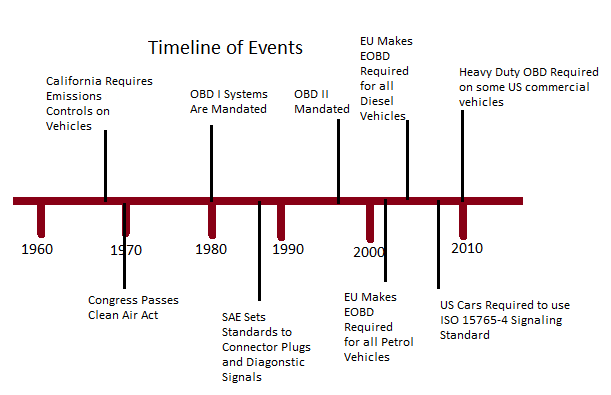
The first generation of on-board diagnostic systems is now known as OBD-I. OBD-I systems were relatively primitive and inconsistent between manufacturers. OBD-II was introduced in the mid 1990's. OBD-II systems are more sophisticated than their predecessors and are more robust in their engine monitoring and control capabilities. All vehicles manufactured after January 1, 1996 are required to have OBD-II systems; although some manufacturers implemented OBD-II as early as 1994. OBD-II standards were originally developed by SAE and later adopted by the EPA and CARB (California Air Resources Board).
OBD-II systems have greater functionality than OBD-I systems, but more importantly there is a much higher level of standardization between manufacturers. OBD-II systems have a standard diagnostic connector and they use standard electrical signal protocols and messaging formats. OBD-II makes it possible to obtain diagnostic information related to emissions controls from any vehicle with a single scanner. An OBD-II compliant vehicle can use any of five communication protocols: SAE J1850 PWM, SAE J1850 VPW, ISO9141-2, ISO14230-4 (KWP2000), or ISO 15765-4/SAE J2480 (CAN). All vehicles sold in the U.S. since the 2008 model year have been required to include the CAN protocol.
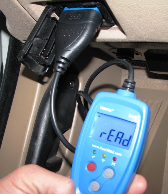
There are two basic ways that OBD-II systems communicate diagnostic information to vehicle operators and technicians. The first way is via the "check engine light" or "MIL" (Malfunction Indicator Light) located on the dashboard display panel. The check engine light will either stay on until the detected problem is fixed or reset itself after a predetermined number of successful engine starts with no error codes. The behavior of the light will depend on the severity of the problem. In any case, the information recorded by the vehicle's computer is stored until the code is cleared by a technician. The check engine light is very useful for spotting problems quickly, but it does not provide specific information about vehicle operation. More detailed diagnostics can be performed with off-board diagnostic scan tools. In response to either an illuminated check engine light or some detectable vehicle malfunction, an automotive technician can attach an OBD-II scan tool to the connector located under the dashboard on the driver side of the vehicle. The scan tool will decipher the error code stored in the vehicle's computer along with many other diagnostic signals to help the technician pinpoint the source of the malfunction. OBD-II scan tools communicate with the vehicle's engine control module (ECM). Depending on the type of scanner and the vehicle manufacturer, there can be as many as 300 diagnostic readings available.
The diagnostic trouble codes that are required by law on the OBD-II are the same for all vehicle manufacturers, but each manufacturer has the freedom to include their own enhanced codes to provide additional information about their electronic systems. Diagnostic trouble codes for the powertrain have the form of "Pxxxx". P1xxx codes refer to manufacturer specific codes which often cover areas that are not emissions related. For example, failures occurring in the ABS, HVAC, airbags and other body and electrical systems may be monitored and stored.
The most common diagnostic trouble codes for the powertrain begin with P0xxx. These are standard codes along with P2xxx and P3xxx that are generic across most manufacturers. For P0xxx codes, the next occurring character describes where the code is coming from. The numbers 0, 1, and 2 refer to fuel and air metering while a 3 indicates the ignition system or a misfire. Auxiliary emissions controls are represented by the number 4 and the number 5 represents vehicle speed controls and the idle control system. 6 refers to the computer output circuit and both 7 and 8 refer to the transmission.
Timeline
- Sensors
-
Oxygen Sensor,
Engine Coolant Temperature Sensor,
Intake Air Temperature Sensor,
Crankshaft Position Sensor,
MAP Sensor,
Fuel Tank Pressure Sensor,
Fuel Temperature Sensor,
Oil Temperature Sensor,
Wiper Washer Fluid Level Sensor,
Vehicle Speed Sensor,
Brake Fluid Level Sensor,
Wheel Speed Sensor,
Accelerometer,
Yaw Rate Sensor,
Master Cylinder Pressure Sensor,
Steering Angle Sensor,
Throttle Position Sensor,
Knock Sensor,
Camshaft Position Sensor,
Fuel Level Sensor
- Actuators
-
Malfunction Indication Lamp (MIL)
- Data Communications
- CAN Bus
- For More Information
- [1] On-Board Diagnostics, Wikipedia.
- [2] OBD-II PIDs, Wikipedia.
- [3]
On-Board Diagnostics(OBD), U.S. Environmental Protection Agency.
- [4]
California On-Board Diagnostics Program, California Air Resources Board.
- [5] Tech Tip: OBD II Engine Diagnostics, Larry Carley, Import Car, Dec. 18, 2008.
- [6] On-Board Diagnostics (OBD) II; Frequently Asked Questions, Ohio EPA website.
- [7] OBD-II (Check Engine Light) Trouble Codes, OBD-Codes.com website.
- [8] Saturday Mechanic: How to Use an OBD-II Scan Tool, YouTube, May 18, 2012.
- [9] Torque & OBDII Android App Review, YouTube, Apr. 5, 2014.
|