Chipping in Friction Element Welding
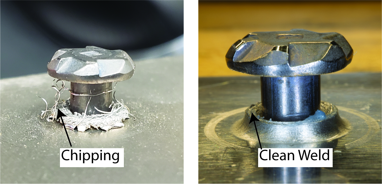
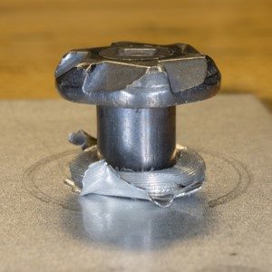
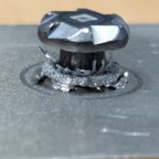
Chipping is observed in particular cases of a FEW Joint.
This high-speed video shows the formation of thin strands of aluminum during the penetration step or chipping.

Friction Element Welding Process Control Parameters:
Spindle Speed: Rotational speed of the element measured in RPM.
Endload: Axial force on the element measured in kN.
Relative Distance/Z-distance: Distance between the tip of the element and the top surface of the top sheet.
Parameters influencing Chipping:
- Alloy Strength
- Element Type
- The coating on the Top Sheet
- EndLoad
Influence of different parameters on chipping:
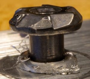
Influence of alloy strength
Chipping is mostly observed in high-strength aluminum alloys. Following images show nest formed after penetration step for AA1100, AA5052, AA6061, AA7021, and AA7075 respectively.
Influence of element type

There are two types of elements (fasteners) commercially available. The selection of friction elements depends on the thickness of the steel sheet. The cylindrical friction element is used for steel sheets with thicknesses in the range of 1 mm to 2.5 mm. The polygonal element is used for steel sheets with thicknesses in the range of 2.5 mm to 4 mm.
It is observed that the polygonal element shows less chipping compared to the cylindrical element.
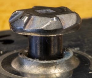
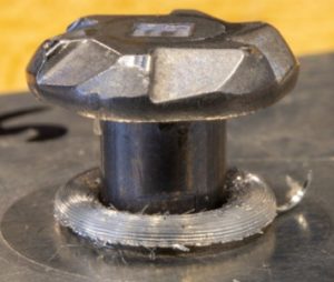
Influence of coating on the top sheet
Coated top sheet
Chipping is higher in sheets with the coated top surface.
Uncoated top sheet
Chipping is lower if the surface of the top sheet is not coated.
Influence of endload
Spindle Speed: 4000 RPM

4 kN

8.5 kN
Spindle Speed: 8500 RPM

4 kN
8.5 kN
Less chipping is observed for higher endload values.